
Compact inserter

a compact inserter and inserter technology, applied in the field of inserters, can solve the problems of labor-intensive saving, and achieve the effect of simplifying and compacting the structure of the inserter

Inactive Publication Date: 2009-05-19
NEOPOST
View PDF16 Cites 0 Cited by
  • Summary
  • Abstract
  • Description
  • Claims
  • Application Information

AI Technical Summary

Benefits of technology

The solution enables a more compact and simpler construction of the inserter, reducing labor costs and improving operational efficiency in small-scale document processing by eliminating the need for separate transport mechanisms, making it more attractive for smaller organizations.

Problems solved by technology

However, also in small organizations that send relatively small numbers of documents, and where the documents to be sent are for a considerable part processed by hand also when being prepared prior to insertion, mechanized insertion could lead to considerable saving of labor.

Method used


Image

  • Compact inserter
  • Compact inserter
  • Compact inserter

Examples


Embodiment Construction

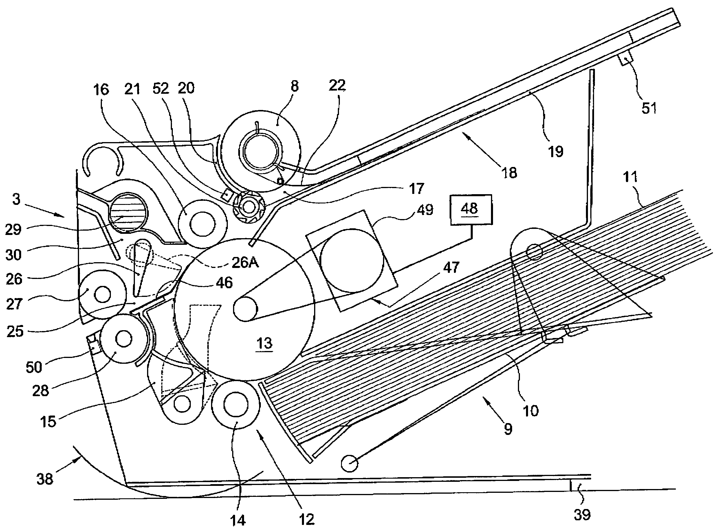
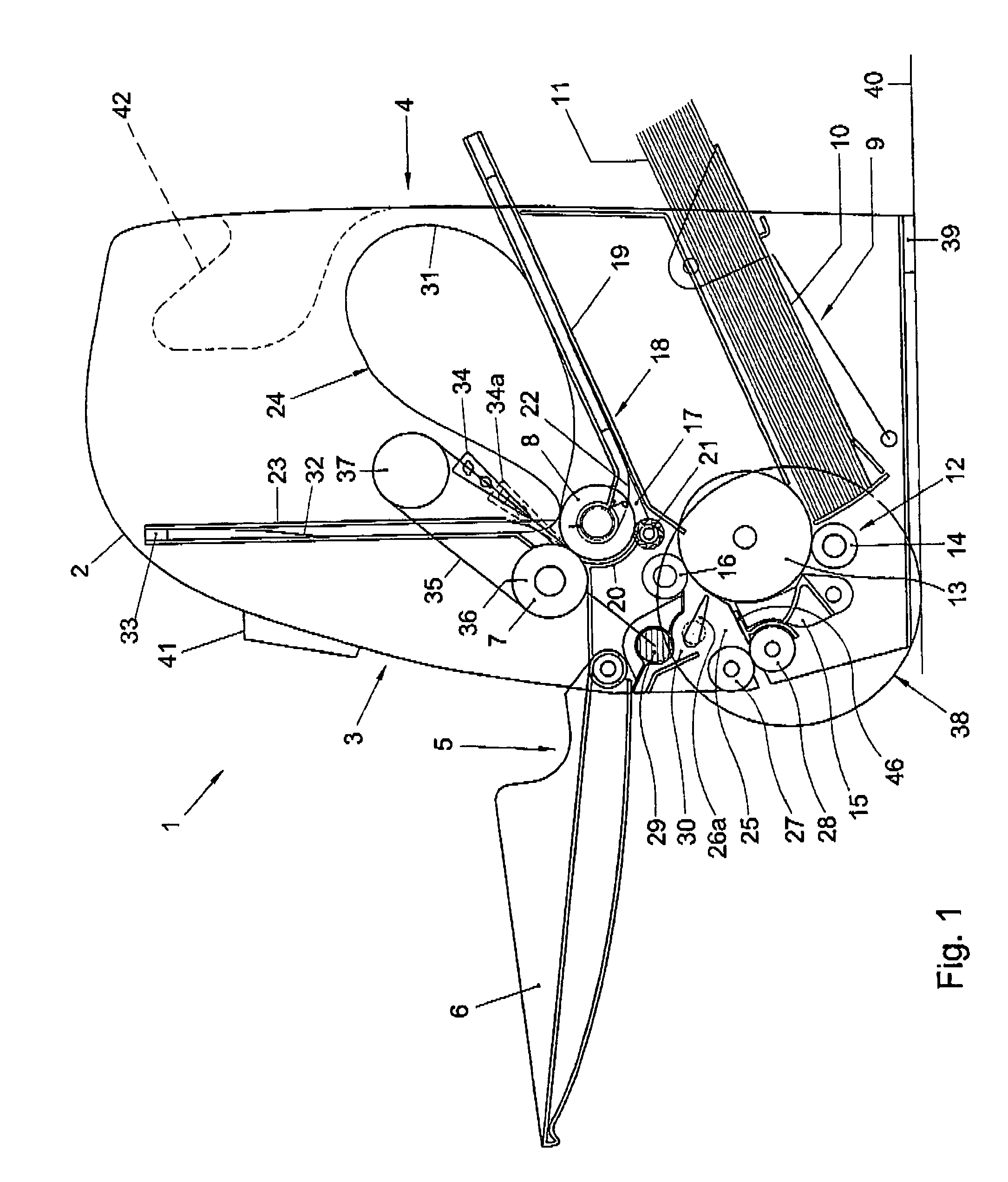
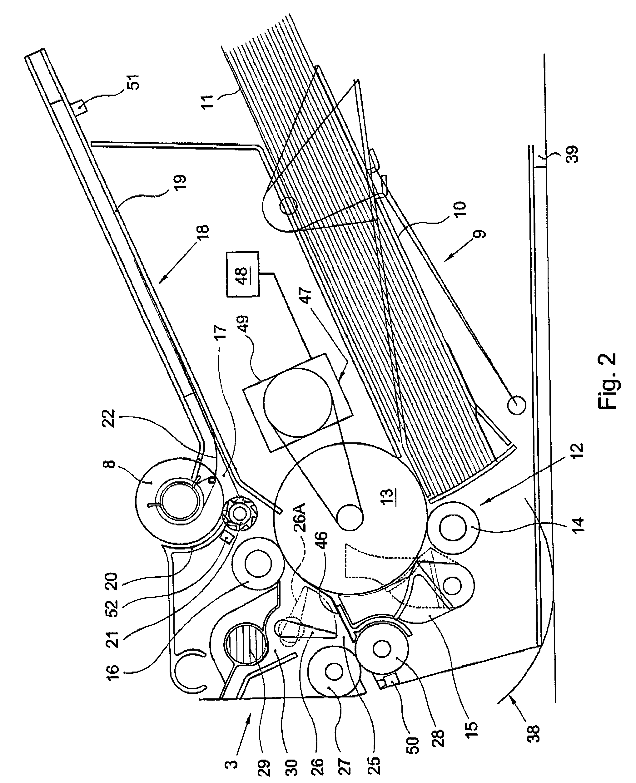
[0010]The inserter 1 according to the example represented in the drawing has a housing 2 with a front side 3 and a rear side 4.

[0011]On the front side 3 is a document feeder 5 with a document holder 6 for taking up a document (not shown) and with a dispenser formed by a pair of folding rollers 7, 8 for dispensing a document from the document holder 6. The document holder 6 at the same time forms a cover of the housing 2, adapted to be hinged between the open position represented and a closed position not represented.

[0012]On the rear side 4 is an envelope feeder 9 with an envelope holder 10 for taking up a stack of envelopes 11 and with a separator 12 for separately dispensing individual envelopes from the holder 10. According to this example, the separator 12 is equipped with a transport roller 13 for taking up envelopes and a separation element in the form of a separation roller 14 for each time stopping next envelopes, so that each time a single envelope can be dispensed off the ...


PUM


Abstract

Inserter provided with an envelope feeder having an envelope supply holder for taking up a stack of envelopes and having a transport roller and a separation element opposite a circumferential portion of the transport roller, for separately dispensing individual envelopes from the envelope supply holder. An envelope transport path extends from the envelope feeder to a stuffing position for transporting envelopes from the envelope feeder to the stuffing position. At least one guide along the envelope transport path downstream of the separation element comprises a flap hold-open element for holding a flap of an envelope held in the stuffing position open, situated opposite a circumferential portion of the transport roller of the envelope feeder.

Description

CROSS-REFERENCE TO RELATED APPLICATIONS[0001]This application claims priority from Dutch Patent Application No. NL 1027940, filed on Dec. 31, 2004.FIELD AND BACKGROUND OF THE INVENTION[0002]This invention relates to an inserter. In U.K. patent No. 1,084,262 an example of such an inserter is disclosed. The inserter includes a system for unstacking envelopes and for opening the flaps of unstacked envelopes. Separate apparatuses for that purpose are known from U.S. Pat. No. 3,747,297, U.S. Pat. No. 3,962,848 and U.S. Pat. No. 6,036,185.[0003]In practice, apparatuses as mentioned above are typically used in mailrooms where large numbers of documents or sets of documents are each to be inserted in an envelope in order to send these documents to addresses.[0004]However, also in small organizations that send relatively small numbers of documents, and where the documents to be sent are for a considerable part processed by hand also when being prepared prior to insertion, mechanized insertio...

Claims


Application Information

Patent Timeline
Patent Type & Authority Patents(United States)
IPC IPC(8): B65H39/00
CPCB43M3/045B43M5/042
Inventor SYTEMA, HERMAN
Owner NEOPOST
Learn More