Wiper blade

A technology for a wiper strip and a stopper is applied in the field of wiper strips, which can solve the problem of not being able to reliably prevent a wiper lip windshield from occupying an undesired angle, and achieve the effect of avoiding interference noise.

Inactive Publication Date: 2010-02-10
ROBERT BOSCH GMBH
View PDF10 Cites 8 Cited by
  • Summary
  • Abstract
  • Description
  • Claims
  • Application Information

AI Technical Summary

Problems solved by technology

However, such wiper strips also do not reliably prevent the wiper lip from occupying an undesired angle relative to the windshield during operation.

Method used


Image

  • Wiper blade
  • Wiper blade
  • Wiper blade

Examples


Embodiment Construction

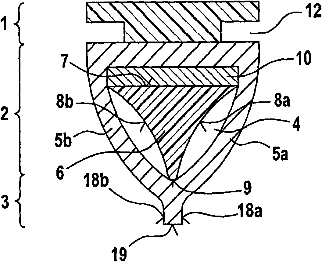
[0020] figure 1 A cross-section of the wiper strip proposed by the invention is shown. The cross section is subdivided into a fastening part 1 and a wiper lip 3 , which are connected to each other by a central part 2 .

[0021] according to figure 1 According to the embodiment, the fixed part 1 has a substantially T-shaped cross-section. Grooves 12 are thus formed on both sides of the wiper strip, on which a fastening device, which is arranged at the end of a wiper arm, can act. The fastening part 1 can now be made of a polymer. figure 1 The shown cross section can be constant over the entire longitudinal extent of the wiper strip. This makes it possible to position the wiper arm arbitrarily along the longitudinal extent of the wiper strip. In another embodiment of the invention, however, the fastening part 1 is arranged only at predetermined positions along the longitudinal extent of the wiper strip, so that a defined positioning of the wiper strip on the arm of the wipe...


PUM


Abstract

The wiper blade has a fastening part, a wiper lip and an elastically connected center part. The center part has a hollow space, which is bounded by two flexible walls. A stopper element is provided toextend in the hollow space based from the fastening part, and bounds the deformation of the center part, when the wiper blade is loaded with a deformed force. The stopper element has three-cornered cross-section, whose base surface represents in direction of the fastening part.

Description

technical field [0001] The invention relates to a wiper strip having a fastening part, a wiper lip and an elastic middle part connecting the wiper lip, wherein the middle part has a cavity delimited by at least two flexible walls , a stop is provided which extends from the fastening part into the cavity and serves to limit the deformation of the central part when the wiper strip is acted upon by a deformation force. Background technique [0002] Wiper strips of the type mentioned at the outset are mainly used in windshield wiper assemblies of motor vehicles. For this purpose, the wiper strip is fastened by its fastening part to a displaceable or pivotable arm and is guided by means of an electric motor over the windshield to be cleaned. The adhering water or adhering dirt is now removed from the glass by the wiper lip. [0003] It is known from the prior art that an elastic intermediate part is arranged between the fastening part and the wiper lip of the wiper strip, the e...

Claims


Application Information

Patent Timeline
Patent Type & Authority Applications(China)
IPC IPC(8): B60S1/38
CPCB60S1/38B60S1/3808B60S2001/3836
Inventor I·奥普特鲁特
Owner ROBERT BOSCH GMBH
Why Eureka
Try Eureka