
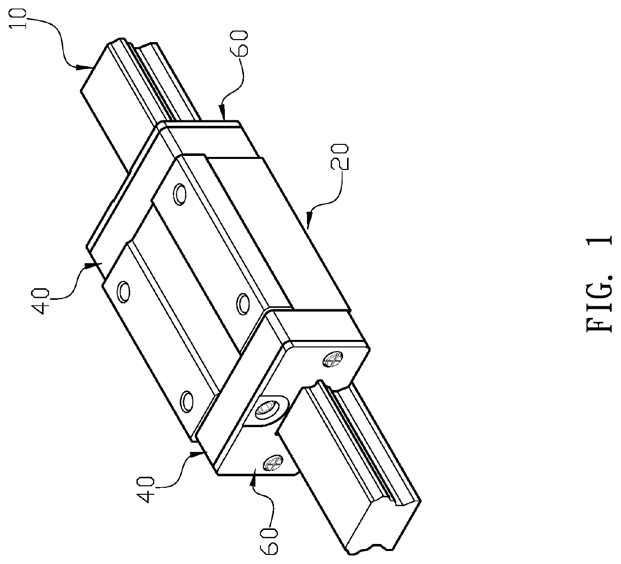
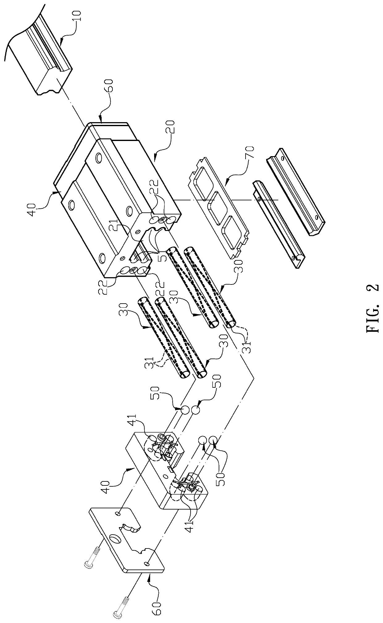
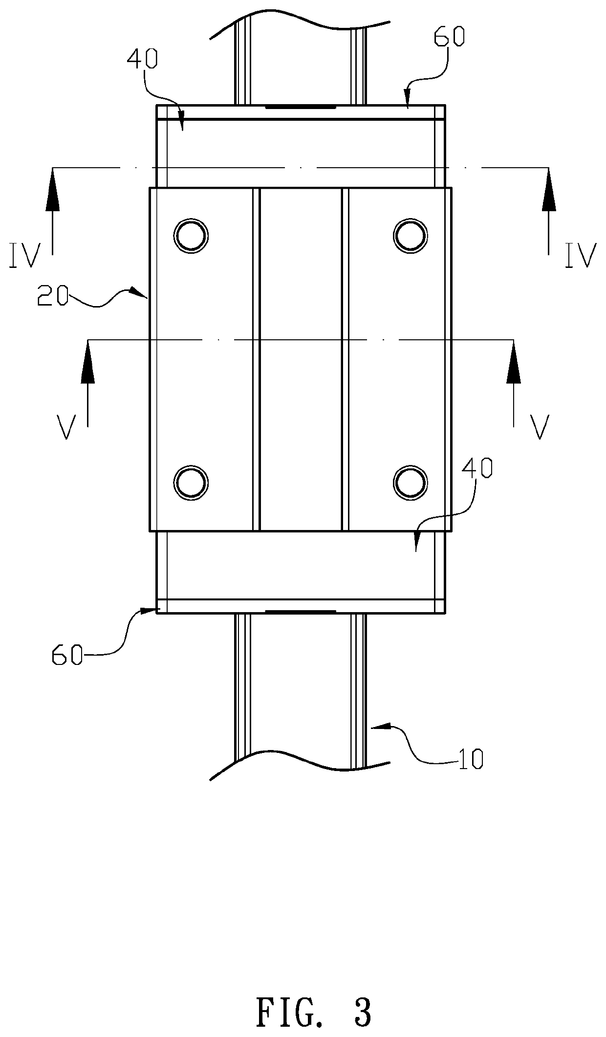
Linear guide apparatus

a technology of linear guide and guide shaft, which is applied in the direction of linear bearings, shafts and bearings, bearings, etc., can solve the problems of disturbing noise and reducing the operation and achieve the effect of prolonging the life of linear guide apparatus and avoiding disturbing nois

Active Publication Date: 2020-12-24
LIN WEI TING
View PDF0 Cites 0 Cited by
  • Summary
  • Abstract
  • Description
  • Claims
  • Application Information

AI Technical Summary

Benefits of technology

The present invention provides a linear guide apparatus that has recirculating tubes with spiral threads and rolling balls that roll laterally, which reduces stress on the rolling balls and increases their life time. The apparatus has a unique design that prevents the rolling balls from supporting more than one load at a time. The diameter of the U-shaped channel is larger than the recirculating tube, which ensures smooth movement and reduces noise. These technical features make this linear guide apparatus more efficient and reliable.

Problems solved by technology

However, the conventional linear guide apparatus has following disadvantages: (i) the linear guide apparatus will only push the balls forward one by one in accordance with the moving direction of the moving part, and may not enable the balls to have lateral flip during recirculating process, so that the load of the ball is adapted to be concentrated at one point of the ball, thereby reducing the operation life of the linear guide apparatus; and (ii) when the diameter of the turning section of the recirculating channel is larger than the diameter of the ball, the row of balls are adapted to have dislocation so as to make the balls having different speeds, thereby causing disturbing noise.

Method used


Image

  • Linear guide apparatus
  • Linear guide apparatus
  • Linear guide apparatus

Examples


Embodiment Construction

[0017]The detailed description set forth below is intended as a description of the presently exemplary device provided in accordance with aspects of the present invention and is not intended to represent the only forms in which the present invention may be prepared or utilized. It is to be understood, rather, that the same or equivalent functions and components may be accomplished by different embodiments that are also intended to be encompassed within the spirit and scope of the invention.

[0018]Unless defined otherwise, all technical and scientific terms used herein have the same meaning as commonly understood to one of ordinary skill in the art to which this invention belongs. Although any methods, devices and materials similar or equivalent to those described can be used in the practice or testing of the invention, the exemplary methods, devices and materials are now described.

[0019]All publications mentioned are incorporated by reference for the purpose of describing and disclos...


PUM


Abstract

A linear guide apparatus may include a guide rail, a carriage block, at least two recirculating tubes, and two end covers. The carriage block has an axial sliding channel formed at a middle portion of a bottom surface thereof, and the carriage block is slidably coupled on the guide rail through the sliding channel. Each of two sides of the sliding channel has at least a sliding groove formed between the carriage block and guide rail. Each sliding groove comprises a plurality of rolling balls installed therein so as to enable the carriage block to slide forward and backward on the guide rail. Each of the sliding grooves is cooperated with a recirculating channel axially penetrating through the carriage block. Each of the recirculating tubes comprises a plurality of spiral threads to enable the rolling balls to have lateral roll at a specific angle when passing therethrough.

Description

FIELD OF THE INVENTION[0001]The present invention relates to a linear guide apparatus and more particularly to a long operating life and low-noise linear guide apparatus.BACKGROUND OF THE INVENTION[0002]The linear guide apparatus is mainly used in the occasion of liner reciprocating motion, which can achieve high-precision linear motion under high load. The function of the linear guide apparatus is to support and guide the moving part, and the moving part can have reciprocating linear displacement in a predetermined direction. Moreover, since the friction type of the linear guide apparatus is the rolling friction, the friction coefficient can be reduced to about one-fifth of the original sliding guidance, which also makes the difference between dynamic friction and static friction smaller when the linear guide apparatus is operated.[0003]A conventional linear guide apparatus comprises a guiding rail and a sliding block, and an elongated groove is formed at a middle portion of a bott...

Claims


Application Information

Patent Timeline
Patent Type & Authority Applications(United States)
IPC IPC(8): F16C29/06
CPCF16C29/06F16C29/0611F16C33/10F16C29/0647
Inventor LIN, WEI-TING
Owner LIN WEI TING
Learn More