Supercharge Your Innovation With Domain-Expert AI Agents!

Oil well stage-cementing metal plate

A technology for steel plates and production wells, used in wellbore/well components, sealing/isolation, earth-moving drilling, etc.

Inactive Publication Date: 2010-02-10
SAUDI ARABIAN OIL CO
View PDF3 Cites 2 Cited by
  • Summary
  • Abstract
  • Description
  • Claims
  • Application Information

AI Technical Summary

Problems solved by technology

This installation will be called Segmented Cement Grout Metal Panels

Method used


Image

  • Oil well stage-cementing metal plate
  • Oil well stage-cementing metal plate
  • Oil well stage-cementing metal plate

Examples


Embodiment Construction

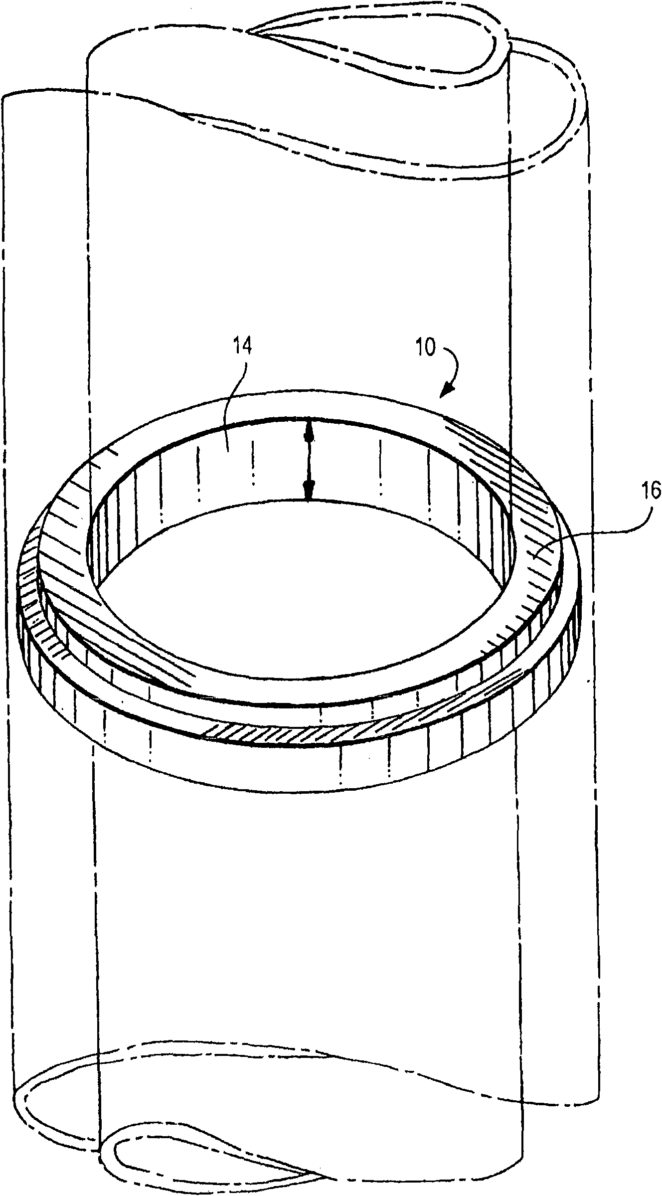
[0028] refer to figure 1 , there is shown a load bearing annulus used in the method of the present invention in place of a segmented cement grouting tool or cement umbrella in an oil well cementing operation to maintain the cement slurry above the loss of circulation zone and between two concentric casing strings steel plate. The plate 10 is annular and has a central circular opening 14 with an inner diameter slightly larger than the outer diameter of the inner sleeve and an outer diameter equal to the offset diameter of the outer sleeve. Preferably the slab is approximately 2.5 inches / 6.25cm thick and is capable of supporting the weight of a column of cement up to 4000ft / 1300m. also in figure 1 In the embodiment shown, the plate is provided with a raised shoulder 16 surrounding the central opening 14 .

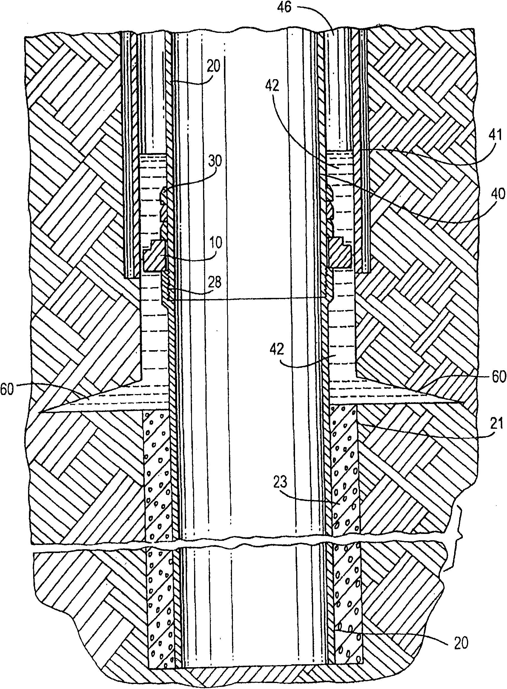
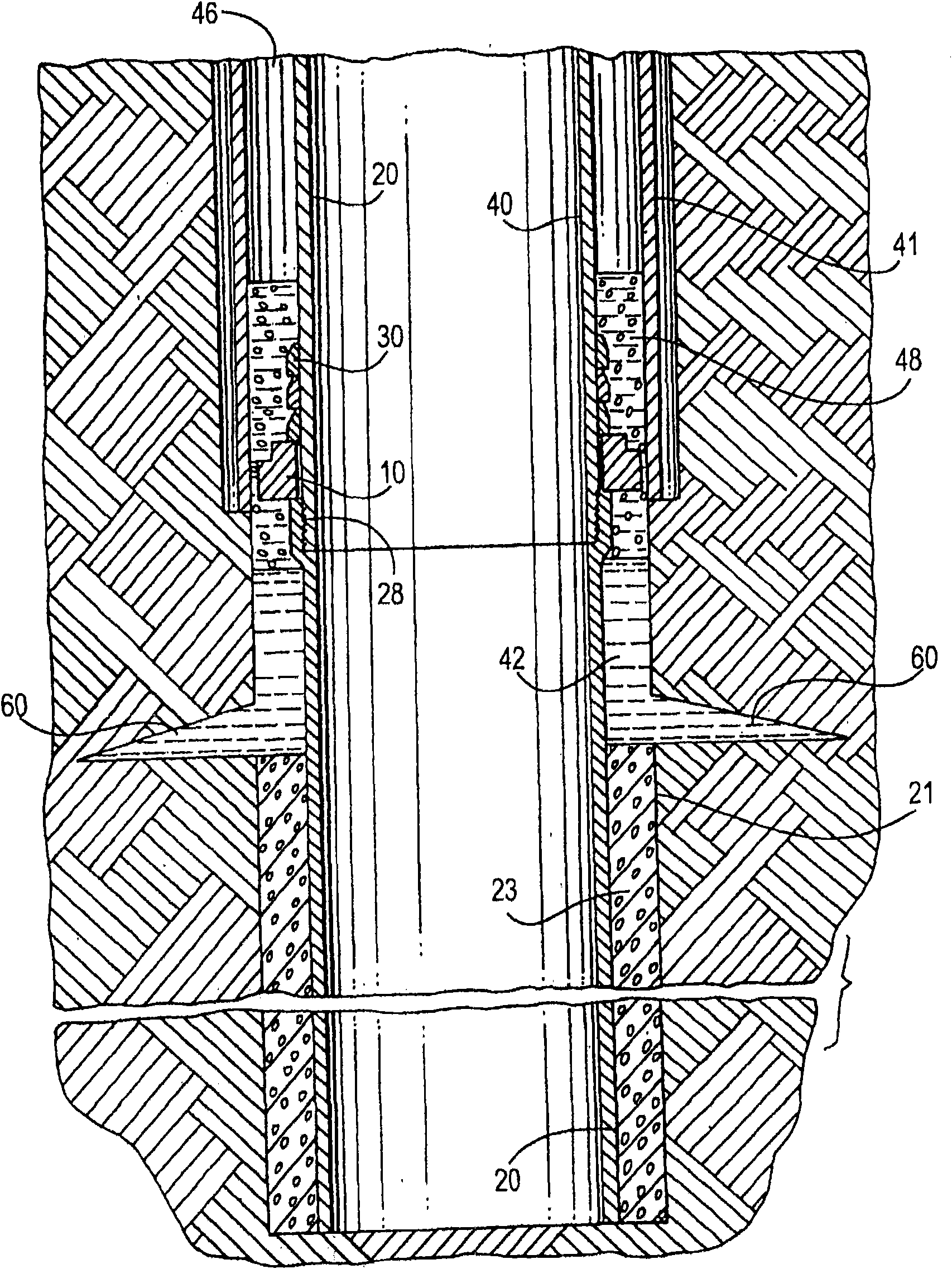
[0029] now refer to figure 2 , will illustrate the step-by-step procedure for placing cement slurry into the annulus between two casing strings, above the loss of circul...


PUM


Abstract

A method and apparatus for use in stage-cementing an oil well in the region of a loss-circulation zone that is proximate an annular space defined by the lower end of an outer casing surrounding an inner casing include a load-bearing annular steel plate of substantial thickness that is positioned on, and maintained stationary relative to the inner casing by supporting and retaining means secured to the inner casing, the outer diameter of the plate being less than the inside diameter of the outer casing so that the plate can be lowered with the inner casing string to the desired location inside of the outer casing and, with a layer of gravel, to provide a seal and support the cement poured into the annulus between the inner and outer casings.

Description

technical field [0001] The present invention relates to the completion of steps in an oil well wherein the annular space between an outer casing extending from the surface and a smaller diameter inner casing is filled with cement. Background technique [0002] Areas of soil, sand, gravel, loose rock and other loose materials encountered during the initial stages of drilling through the ground. To stabilize the casing string surrounding the production tubing string in this region of unstable subterranean material, the outer casing is lowered as the drill bit is advanced. When a more stable formation is reached, the outer casing is terminated and the inner casing is lowered to complete drilling. [0003] The outer casing can extend to a depth of 1,000 feet / 300 meters, or more, and is required to provide a barrier to the drilling operation and protect and stabilize the inner casing in the upper layers of the surface, where the subsurface is the loose material. Once drilling r...

Claims


Application Information

Patent Timeline
Patent Type & Authority Applications(China)
IPC IPC(8): E21B33/00
CPCE21B33/1293E21B33/146E21B33/13E21B33/136
Inventor O·J·埃斯梅尔
Owner SAUDI ARABIAN OIL CO
Features
  • R&D
  • Intellectual Property
  • Life Sciences
  • Materials
  • Tech Scout
  • Unparalleled Data Quality
  • Higher Quality Content
  • 60% Fewer Hallucinations
Learn More