Warp beam

A warp beam and axial technology, applied in the field of warp beams, can solve the problems of time-consuming and reduce the risk of falling and messing up

Active Publication Date: 2010-02-17
KARL MAYER STOLL R&D GMBH
View PDF0 Cites 1 Cited by
  • Summary
  • Abstract
  • Description
  • Claims
  • Application Information

AI Technical Summary

Problems solved by technology

The preparations for the production of this warp thus also consume a considerable amount of time which is not devoted to the production process of the warp itself

Method used


Image

  • Warp beam
  • Warp beam
  • Warp beam

Examples


Embodiment Construction

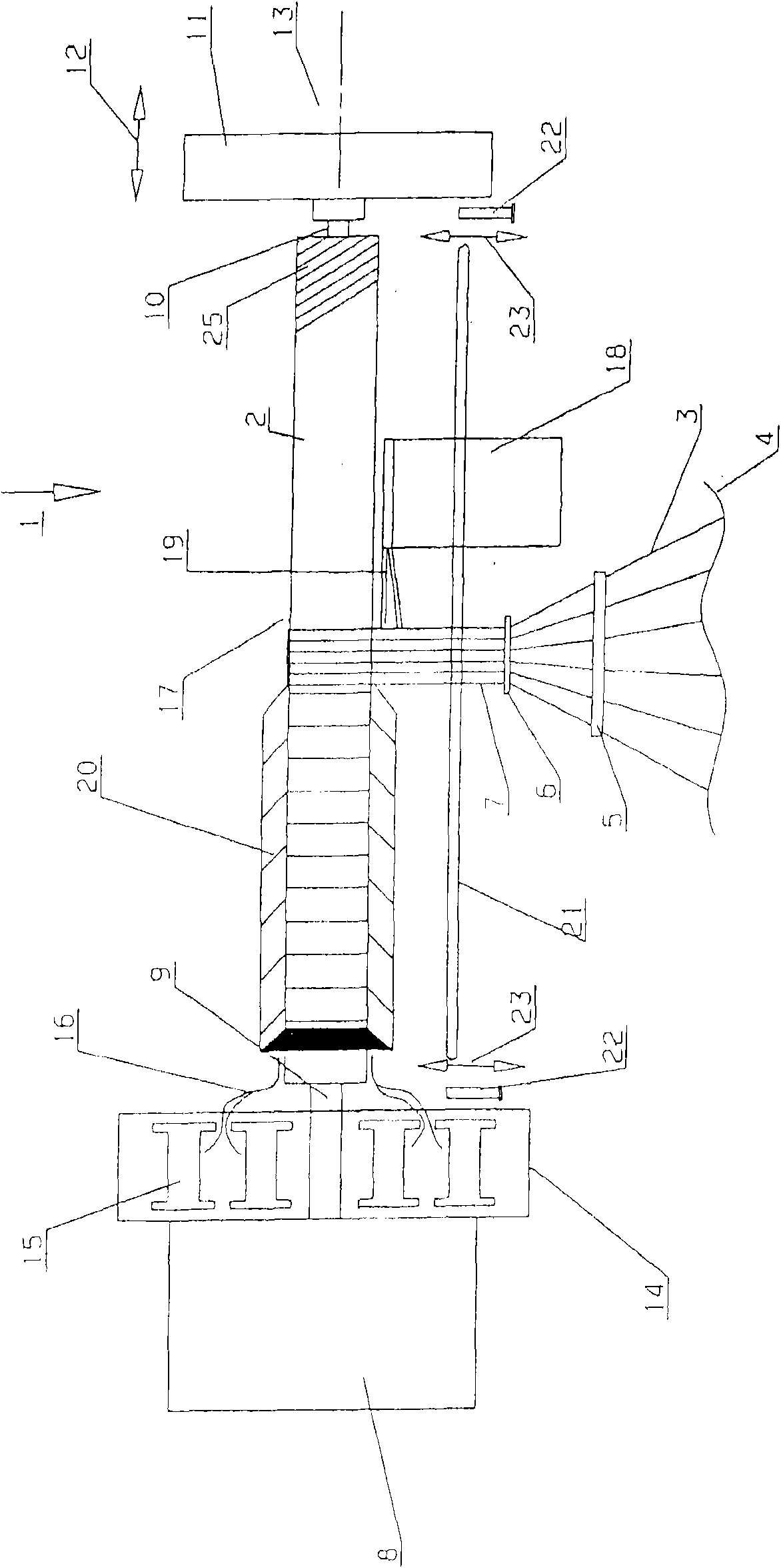
[0022] figure 1 A warping device 1 is shown in a high-level overview with a winding frame designed as a warp beam 2 , on which a thread 3 drawn from a creel 4 is wound. The thread 3 is guided through the warp dividing device 5 and then through the warping reed 6 where it is finally merged into a belt 7 .

[0023] The warp beam 2 is connected to a rotary drive 8 . For this purpose, the warp beam 2 has a warp beam strut 9 at an axial end, which is formed in a rotationally fixed engagement with a rotary drive 8 by means of a clamping head, not shown in detail.

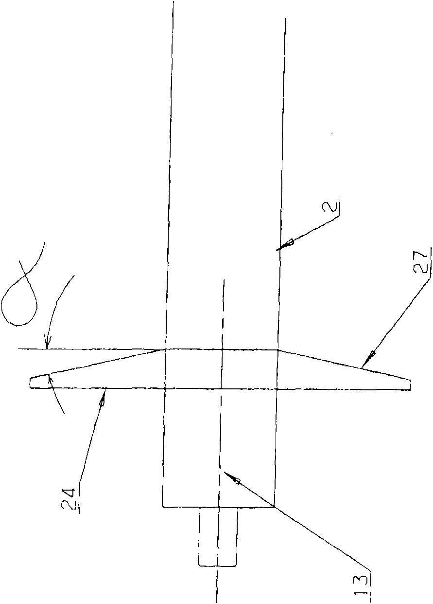
[0024] At its opposite end, the warp beam 2 is provided with a further warp beam support 10 , which is supported in a butt support 11 . The docking support 11 is movable in the direction of the double arrow 12 , that is to say parallel to the axis 13 of the warp beam 2 . Thus, the warp beam 2 can be engaged at one end with its warp beam support 9 and the rotary drive 8, and then the other end can be supported by the do...


PUM

PropertyMeasurementUnit
angleaaaaaaaaaa

Abstract

The wrap beam (2) has a shaft and at least a wrap beam disk (24). For the realization of short production time in the process of producing warp threads, the wrap beam disk (24) has a conical formed support surface (27).

Description

technical field [0001] The invention relates to a warp beam having a shaft and at least one warp beam disk. Background technique [0002] The warp beams are used for winding warp threads, ie warp bundles, which are used later in textile manufacture. Textile mills and weaving mills especially require warp yarns. [0003] There are various possibilities for producing warp threads. One possibility consists in drawing a certain number of threads from the creel and winding them in the form of a tape or narrow tape onto the warping cylinder. When the warp thread reaches the desired length, that is to say a certain number of loops are wound, the narrow tape moves a distance equal to its width and is wound next to the coil produced up to that time. In order to prevent the wire from falling off at the end face of the coil, it is known to design the end face conically. This is achieved by the fact that the warping cylinder has a cone at the axial end, wherein the strip moves later...

Claims


Application Information

Patent Timeline
Patent Type & Authority Applications(China)
IPC IPC(8): D02H13/32
CPCD02H13/30D02H9/00D02H13/32
Inventor M·富尔
Owner KARL MAYER STOLL R&D GMBH
Why Eureka
Try Eureka