Stepless rapid extendable multipod with built-in power supply

a multi-pod, built-in technology, applied in the direction of machine supports, electric apparatus casings/cabinets/drawers, transportation and packaging, etc., can solve the problems of extending and locking down slowly, complicated assembly, and large amount of parts, and achieves easy mounting and dismounting of apparatus, simple structure, and strong support

Active Publication Date: 2016-03-24
CHEN KAIZHI
View PDF6 Cites 16 Cited by
  • Summary
  • Abstract
  • Description
  • Claims
  • Application Information

AI Technical Summary

Benefits of technology

[0008]In one embodiment, the stepless extendable device includes an apparatus mount adaptor, an extendable pole set, pole plugs, pole locks, guiding and positioning rings (GAP rings) and unidirectional safety valves (UDS valves). Pole plugs are inserted inside the pole set and affixed at the two ends of the pole set. Pole locks are used to lock down the poles of the extendable pole set. An extendable pole set includes at least two poles of different diameters. In the order from largest to smallest diameter, a larger pole sleeves a smaller pole. A pole lock is placed on the outside of every pole of smaller diameters. A GAP ring is placed between every pair of inner and outer poles to guide and position each pole. The pole lock utilizes an eccentric axis to force an axial shift between an outer and inner pole to form a mechanical lock. A pole lock sleeving an inner pole can move up and down freely, thus capable of creating a lock at various heights.
[0009]A UDS valve of said stepless extendable device is installed at the lower end of every inner pole. When an inner pole drops down with a heavy object on top, the rapid falling motion will compress the air inside the outer pole. The faster the falling, the larger is the reaction force to slow down the falling. Thus, a user will not be harmed by the rapid falling of the extendable poles.
[0010]In one embodiment, the supporting element includes at least two legs, a corresponding number of leg braces, a leg connector and a divaricating plate. One end of each leg is hinged on the divaricating plate. In one embodiment, each leg has a hinged foot which can be folded up. Folding down the hinged feet and pinning them into the ground will stabilize the multipod for operation on dirt ground or grass. One or several of the legs of the multipod may be telescopic and extend and lock steplessly. This arrangement guarantees the mounted apparatus to maintain leveled operation even though the ground is not horizontally leveled. One end of each leg brace is hinged at the leg connector. The other end of the leg brace sleeves and slidably connects to a leg. The center of the divaricating plate has a hole for the stepless extendable device (SED) to pass through, thereby allowing one end of the SED to be affixed to the leg connector.
[0011]In one embodiment, the power supply system includes a power supply control (PSC) and high energy power supplies hidden inside the legs and / or the SED to supply power to the apparatus mounted on the multipod. In one embodiment, a power supply is inserted into each leg and the SED. The PSC is installed inside the divaricating plate of the supporting element. Each power supply is connected electrically to the PSC. The PSC controls the discharging order of the power supplies. In one embodiment, the PSC provides a charging socket and a discharging socket for apparatus and charger connections. The PSC also has a power supply status indicator. When a power supply is exhausted, the PSC will discharge from the next power supply automatically and so on. By placing the power supplies inside the legs and / or SED, the weight of the power supplies assures a low center of gravity and the stability of the multipod.
[0014]The advantages of the present invention include fewer parts, simple structure, sturdy support, easy mounting and dismounting of apparatus.

Problems solved by technology

These traditional tripod devices have several drawbacks such as: lot of parts, complicated assembly, high production cost, extending and locking down slowly.
These approaches have limited power capacity because a tripod has limited storage space.
Wiring harness is cumbersome because attaching batteries below the center pole would require running wires from the battery below to the tripod head above (as described in U.S. Pat. No. 6,902,294 B2).
All these drawbacks limit the portability of a tripod.
Tipping over will also tip and break the supported apparatus.

Method used


Image

  • Stepless rapid extendable multipod with built-in power supply
  • Stepless rapid extendable multipod with built-in power supply
  • Stepless rapid extendable multipod with built-in power supply

Examples


Embodiment Construction

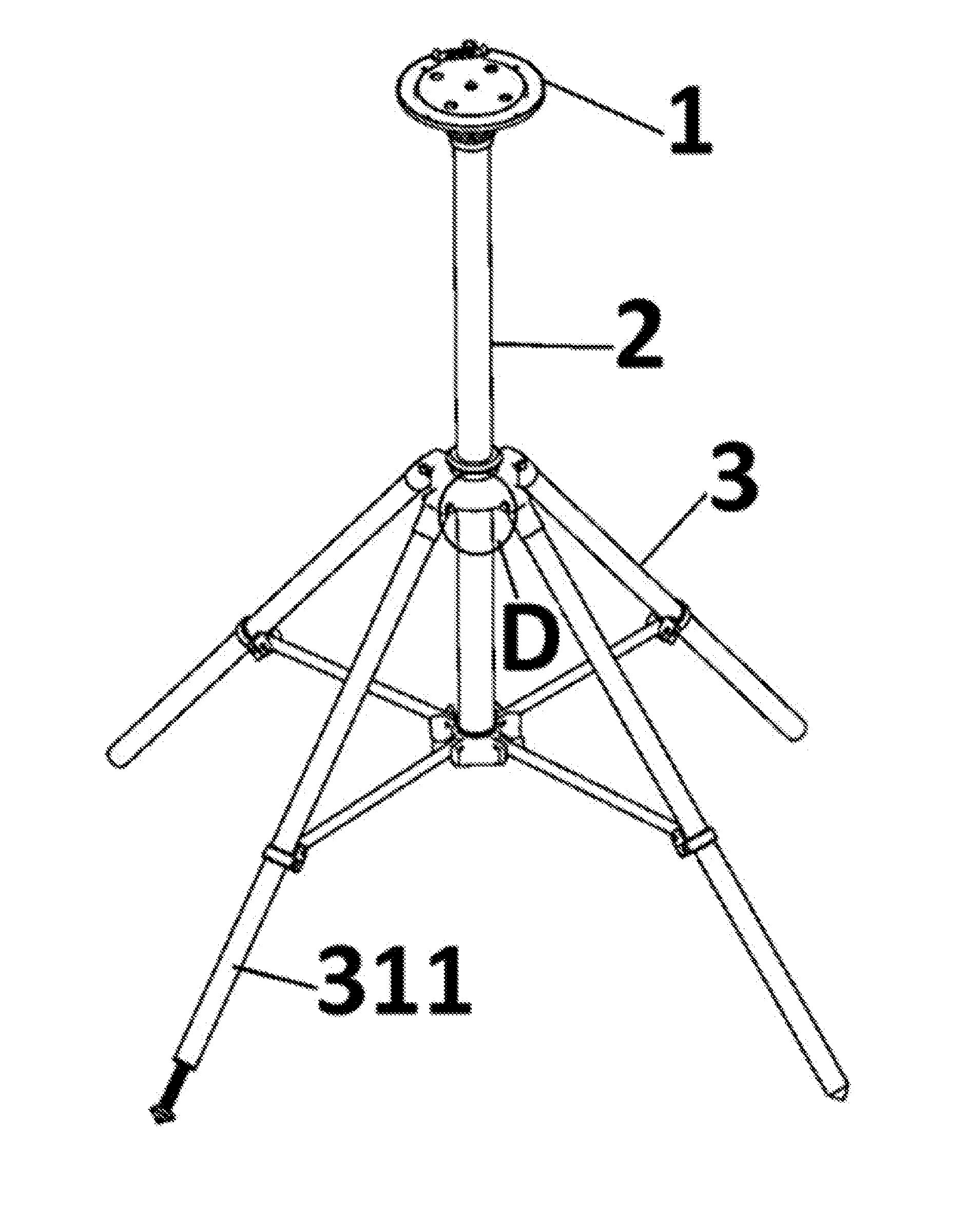
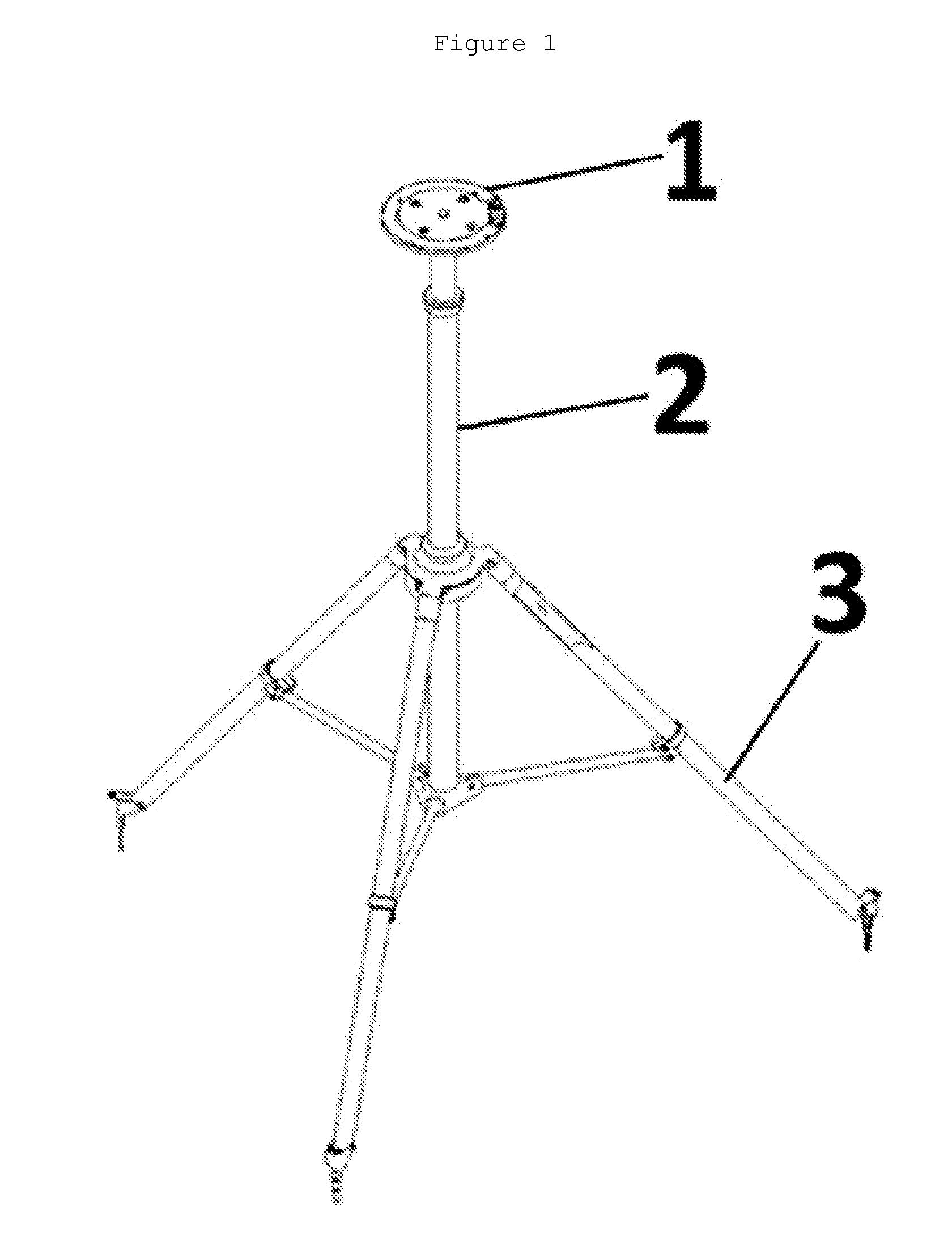
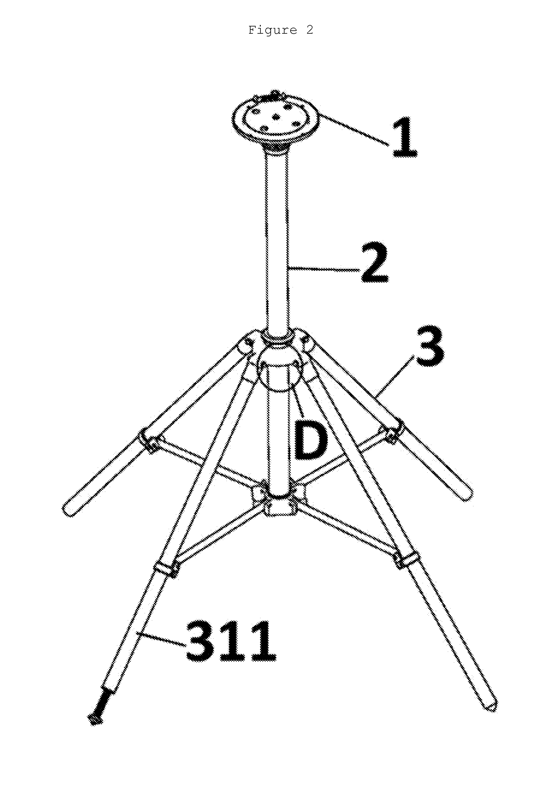
[0039]In the following description, several embodiments of the invention are described. For purposes of explanation, specific configurations and details are set forth in order to provide a thorough understanding of the embodiments. In addition, to the extent that orientations of the embodiments are described as “top”, “bottom”, “front”, “back”, “left”, “right” and the like, these wordings are to aid the reader in understanding the embodiments and are not meant to be limiting physically. It is apparent to a person skilled in the art that the present invention may be practiced without specific details. The invention will be better understood by reference to the embodiments which follow, but those skilled in the art will readily appreciate that the specific embodiments are for illustrative purposes only and should not limit the scope of the invention which is defined by the claims which follow thereafter. It is to be noted that the transitional term “comprising” or “including”, which i...


PUM


Abstract

This invention provides an extendable multipod for mounting an apparatus, comprising: a) an apparatus mount that allows rapid mounting and dismounting of an apparatus, wherein the apparatus mount is attached to one end of an extendable device; b) an extendable device comprising a plurality of tubular poles which are mounted so as to be telescopically and axially slidable relative to each other between an extended position and a retracted position, and the extendable device is attached to a supporting element; and c) a supporting element comprising a plurality of legs that are connected to a divaricating plate, wherein the extendable device is inserted through the divaricating plate to affix on a leg connector, and the leg connector is connected to the plurality of legs by a plurality of braces. Furthermore, the extendable multipod comprises a built-in power supply.

Description

[0001]The application claims benefit of U.S. Ser. No. 62 / 053,757, filed Sep. 22, 2014 and Chinese Application No. 201510016842.0, filed Jan. 13, 2015. The content of the preceding applications are hereby incorporated by their entireties by reference into this application. Throughout this application, various publications are referenced. Disclosures of these publications in their entireties are hereby incorporated by reference into this application in order to more fully describe the state of the art to which this invention pertains.FIELD OF INVENTION[0002]This invention relates generally to a multipod with stepless extendable device and built-in power supply.BACKGROUND OF INVENTION[0003]Tripods are usually used to support apparatus to work at certain height. In the market today, the tripods for lights, telescopes, cameras, camcorders and microphones usually include an extendable pole set of two or more poles or telescopic legs to change height. Most extendable devices use off-center...

Claims


Application Information

Patent Timeline
Patent Type & Authority Applications(United States)
IPC IPC(8): F16M11/28F16M11/04F16M11/08F16M11/24F16M11/42H02J1/00H02J7/00
CPCF16M11/28F16M11/041F16M11/245H02J7/007F16M11/42F16M11/08H02J1/00F16M11/247F16M11/34
Inventor CHEN, KAIZHITSE, GLENN, MANKITGAO, GUOHUAHUANG, YONGSENLI, XINGCHAO
Owner CHEN KAIZHI
Why Eureka
Try Eureka