Method and device for controlling signaling traffic

A flow control and signaling technology, applied in the field of signaling flow control, can solve the problems of fixed flow at the interface, system crash, unpredictable signaling flow at the sending end and receiving end, etc., so as to solve the technical bottleneck and achieve efficient and reliable transmission. Effect

Inactive Publication Date: 2010-02-17
ZTE CORP
View PDF0 Cites 3 Cited by
  • Summary
  • Abstract
  • Description
  • Claims
  • Application Information

AI Technical Summary

Problems solved by technology

[0005] The technical problem to be solved by the present invention is to provide a signaling flow control method and device to solve the unforeseeable signaling flow at the sending end and the receiving end and the fixed flow at the interface between the baseband subsystem and the radio frequency subsystem, resulting in interruption of communication control and system crashes The problem

Method used


Image

  • Method and device for controlling signaling traffic
  • Method and device for controlling signaling traffic
  • Method and device for controlling signaling traffic

Examples


Embodiment Construction

[0050] The present invention will be further described below in conjunction with the accompanying drawings and specific embodiments.

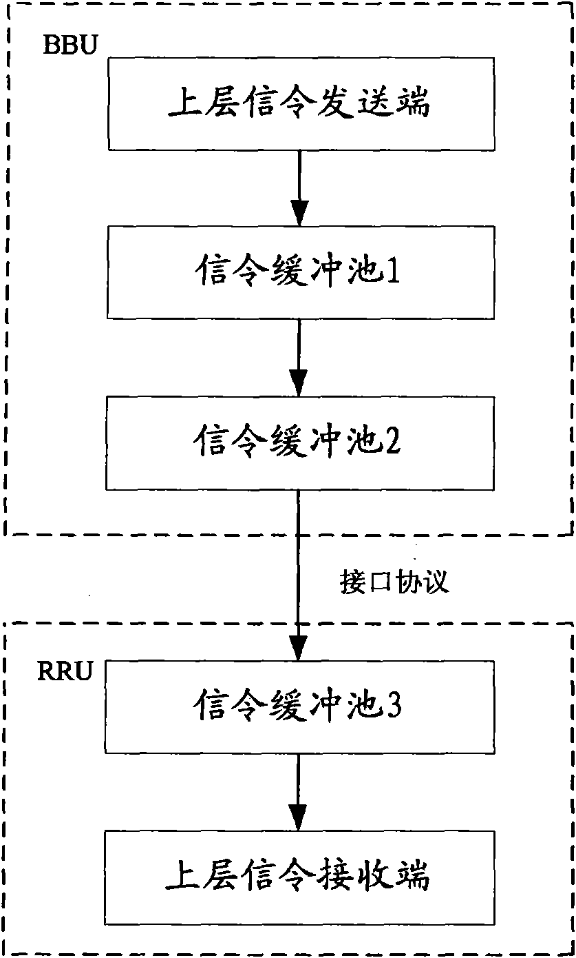
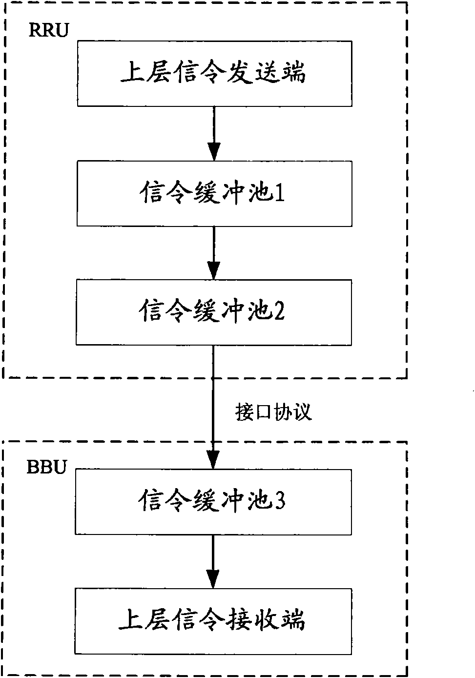
[0051] Such as figure 1 As shown, the forward sending end is BBU, and the receiving end is RRU; figure 2 As shown, the reverse sending end is the RRU, and the receiving end is the BBU.

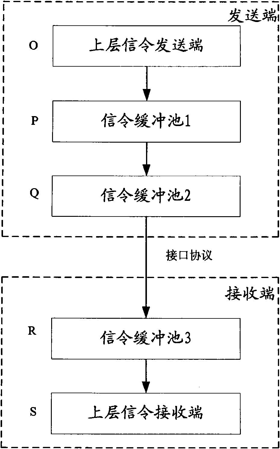
[0052] Such as image 3 As shown, there is no distinction between the forward and reverse, and it is only divided into the sending end and the receiving end. image 3 At the sending end, point O is the sending end of the upper layer signaling (the instantaneous flow of signaling from point O to point P is unpredictable here), and point O determines whether to write down a block according to the blocking state of the next node P. Frame or multi-frame signaling. At point S at the receiving end, one or more frames of signaling are taken from the signaling buffer pool 3 at point R (similarly, the instantaneous traffic at this time is unpredictable). However, ...


PUM


Abstract

The invention discloses a method and a device for controlling signaling traffic. A sending end is provided with a first signaling buffer unit and a second signaling buffer unit, and a receiving end isprovided with a third signaling buffer unit. During signaling transmission, the method comprises that: when sending the upper signaling, the sending end judges states of the first signaling buffer unit and the second signaling buffer unit, writes the upper signaling into the first signaling buffer unit when the first signaling buffer unit is not blocked, takes data out from the first signaling buffer unit to carry out coding when the second signaling buffer unit is not blocked, then writes the coded data into the second signaling buffer unit, and sends the data in the second signaling bufferunit to the receiving end through an interface protocol; and the receiving end decodes the received data and then writes the decoded data into the third signaling buffer unit, and takes the upper signaling out from the third signaling buffer unit by frame. By adopting synchronous coordinate work of a plurality of buffer areas, the method and the device solve the technical defect of signaling interaction between the prior BBU and the RRU, and ensure efficient and reliable transmission of the signaling.

Description

technical field [0001] The present invention relates to the field of flow control in the field of wireless communication, more specifically, to a signaling flow control method between a base band subsystem (Base Band Unit, referred to as BBU) and a radio frequency subsystem (Remote Radio Frequency Unit, referred to as RRU) and devices. Background technique [0002] Between the baseband subsystem BBU and the radio frequency subsystem RRU, the signaling exchange takes one frame as the unit. Once the transmission protocol between the BBU and the RRU is fixed, the bandwidth of the signaling is also fixed. Generally, signaling transmission is bidirectional. Here, the forward direction is defined as the baseband BBU sends signaling to the radio frequency RRU, and the reverse direction is defined as the RRU sends signaling to the BBU. [0003] During signaling interaction, the instantaneous traffic at the receiving end and the sending end is unpredictable. Usually, a specific pro...

Claims


Application Information

Patent Timeline
Patent Type & Authority Applications(China)
IPC IPC(8): H04L12/56H04B7/26H04Q7/30H04L1/00H04W28/10
Inventor 夏中敬杜超张攀科孙涛彭为国
Owner ZTE CORP
Why Eureka
Try Eureka