

Localization system for an earth moving machine
A technology for earthwork and location determination, which is applied to special electromagnetic/magnetic detection, earthmoving machines/shovels, buildings, etc. during transportation, and can solve problems such as damage to sensors.
- Summary
- Abstract
- Description
- Claims
- Application Information
AI Technical Summary
Problems solved by technology
Method used
Image

Examples
Embodiment Construction
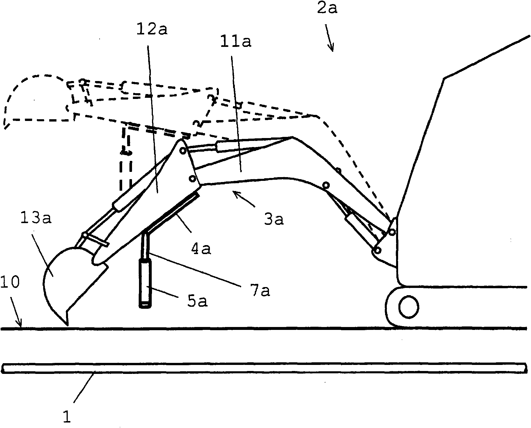
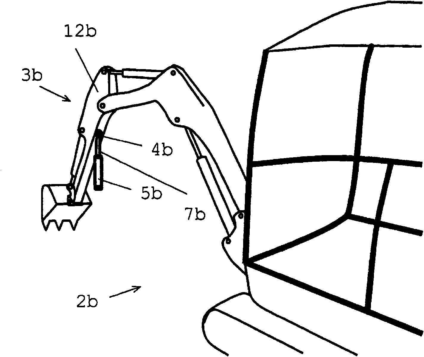
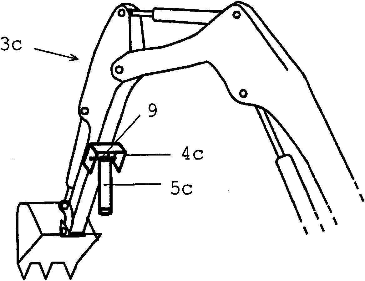
[0043] figure 1 Shown is an excavator 2 a which, as an earth-moving machine, has a position determination system according to the invention. The excavator 2a travels on the ground surface 10 to be excavated. For example, excavation work is part of building roads or laying wires or pipelines. Below the ground surface to be excavated there is already laid a supply line 1 as an underground object, where the supply line 1 emits an electromagnetic field. The excavator 2 a has an excavator arm 3 a , which as working parts has a first arm part 11 a and a second arm part 12 a as well as a bucket 13 a , each of which can be adjusted in height by means of hydraulic cylinders. On the second arm part 12a are arranged a fixing part 4a, a flexible connection part 7a and a detection part 5a as parts of the position determination system according to the invention, where the fixing part 4a is configured to be fixed magnetically on the second arm part The upper housing and is used for the in...
PUM
 Abstract
Description
Claims
Application Information