Vehicle localization system

a technology of vehicle position and localization system, which is applied in the direction of process and machine control, navigation instruments, instruments, etc., can solve the problem that the driving area lacks the features stored in the map data to accurately determine the vehicle position, and achieve the effect of increasing the accuracy of positional determination and accurate determination of the vehicle position

Active Publication Date: 2017-02-02
NISSAN MOTOR CO LTD
View PDF2 Cites 59 Cited by
  • Summary
  • Abstract
  • Description
  • Claims
  • Application Information

AI Technical Summary

Benefits of technology

[0007]It has been discovered that in vehicle localization systems that compute the position of a vehicle by comparing an image of a stored three dimensional map and a camera image, some drivable areas lack sufficient features stored in map data to accurately determine the vehicle position.
[0008]It has been discovered that to increase the accuracy of positional determination two localization system can be employed. Thus, in one disclosed embodiment, a vehicle localization system comprises a first localization system, a second localization system, and a controller. The first localization system is configured to determine a location of the vehicle using a first set of data. The second localization system is configured to determine a location of the vehicle using a second set of data. The controller is configured to switch from the first localization system to the second localization system when the first set of data is less than a predetermined amount.
[0009]In one embodiment, a method of operating a vehicle localization system comprises switching from a first localization system to a second localization system when a set of data is less than a predetermined amount.

Problems solved by technology

It has been discovered that in vehicle localization systems that compute the position of a vehicle by comparing an image of a stored three dimensional map and a camera image, some drivable areas lack sufficient features stored in map data to accurately determine the vehicle position.

Method used


Image

  • Vehicle localization system
  • Vehicle localization system
  • Vehicle localization system

Examples


Embodiment Construction

[0018]Selected embodiments will now be explained with reference to the drawings. It will be apparent to those skilled in the art from this disclosure that the following descriptions of the embodiments are provided for illustration only and not for the purpose of limiting the invention as defined by the appended claims and their equivalents.

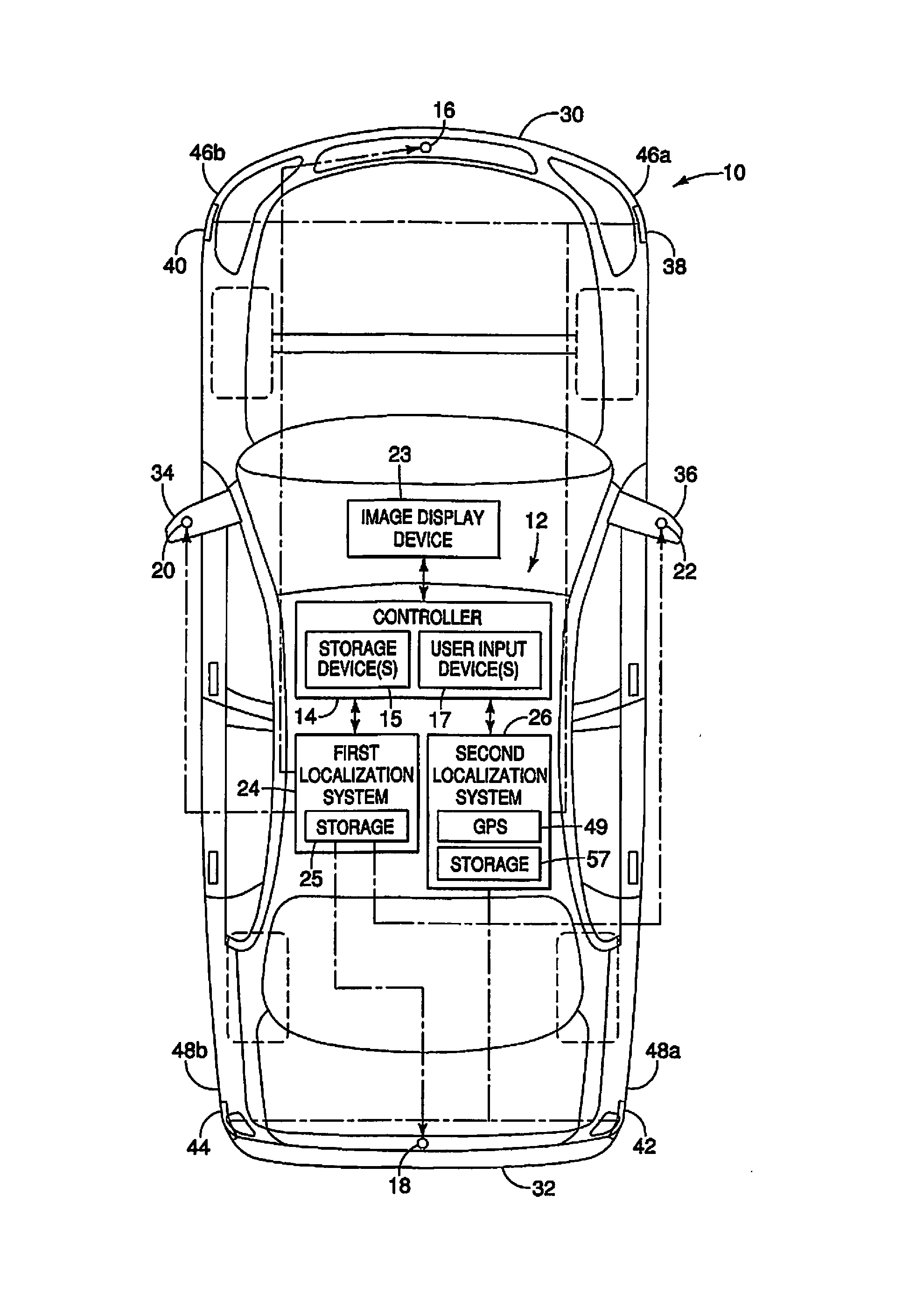
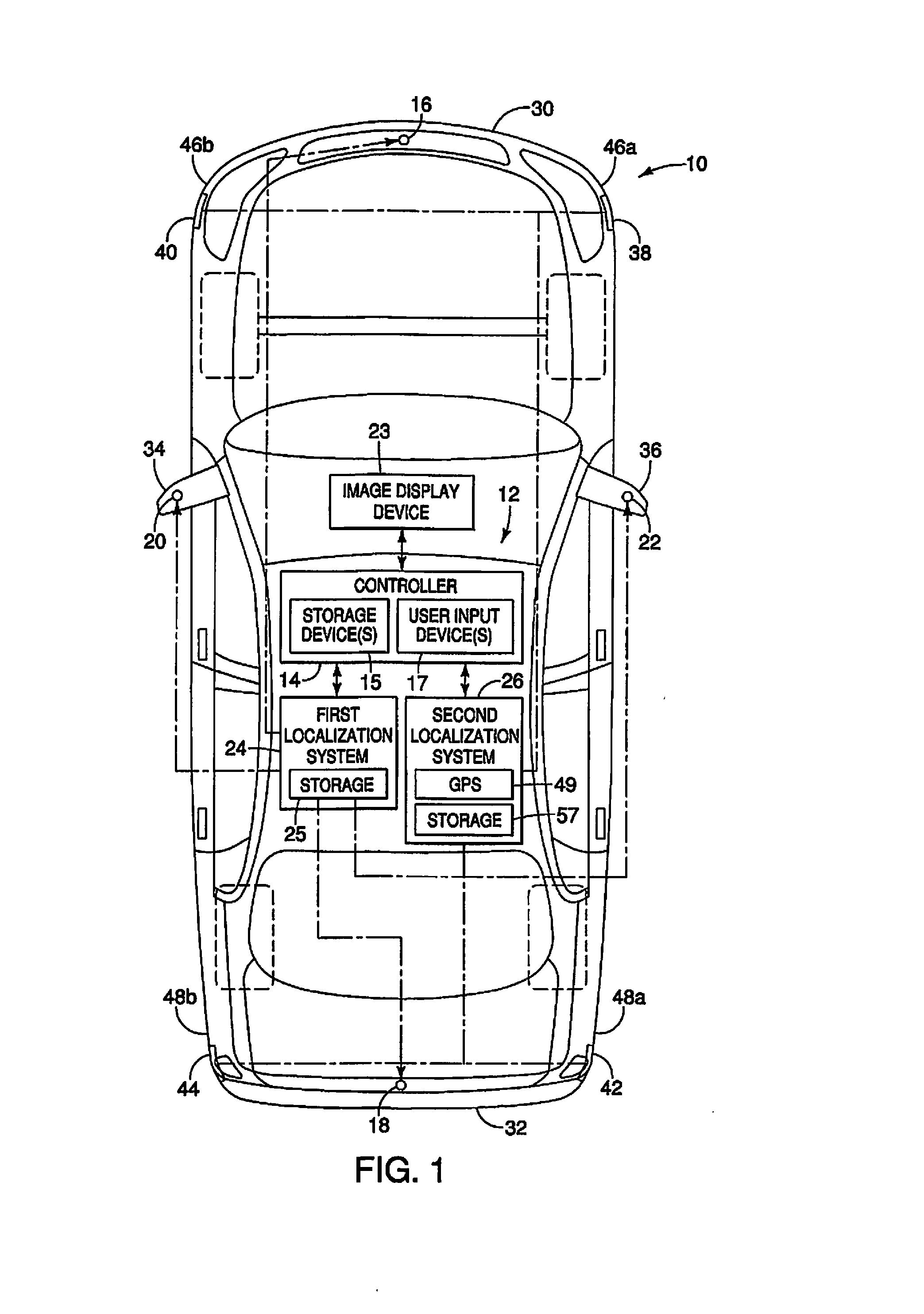
[0019]The disclosed embodiments are for a vehicle localization system 12 on a host autonomous vehicle 10 that selectively switches between two localization systems based on predetermined conditions. It is noted that the vehicle localization system 12 may be used in a non-autonomous vehicle, if desired. Thus, the vehicle localization system 12 has improved vehicle control characteristics and is capable of provided autonomous control in a variety of areas. As is understood, the autonomous vehicle 10 has any additional systems and devices necessary for vehicle operation (both autonomous and not autonomous), which are not described herein.

[0020]Referr...


PUM


Abstract

A vehicle localization system includes a first localization system, a second localization system, and a controller. The first localization system is configured to determine a location of the vehicle using a first set of data. The second localization system is configured to determine a location of the vehicle using a second set of data. The controller is configured to switch from the first localization system to the second localization system when the first set of data is less than a predetermined amount.

Description

BACKGROUND[0001]Field of the Invention[0002]The present invention generally relates to a vehicle localization system for an autonomous vehicle. More specifically, the present invention relates to a vehicle localization system for an autonomous vehicle that selectively switches between two localization systems based on predetermined conditions.[0003]Background Information[0004]As understood in the art, autonomous vehicles generally include a vehicle control system that is capable of performing driving operations to guide the vehicle to a predetermined destination without input from the driver or with only minimal input from the driver. The vehicle control system typically uses a plurality of high speed cameras to monitor areas surrounding the vehicle. The cameras detect, for example, traffic lights, signs, intersection markers, other vehicles and obstacles, and provide visual data to the vehicle control system.[0005]Conventional vehicle localization systems compute the position of a ...

Claims


Application Information

Patent Timeline
Patent Type & Authority Applications(United States)
IPC IPC(8): G01C21/32G01S19/47G01C21/16G05D1/02G05D1/00
CPCG01C21/32G05D1/0246G05D1/0274G05D2201/0213G05D1/0088G01C21/165G01S19/47G05D1/0278F16H59/44G01C21/26G05D1/0268G06V20/56G01C21/1652G01C21/30G01C21/1656
Inventor KOJO, NAOKI
Owner NISSAN MOTOR CO LTD
Why Eureka
Try Eureka