
Holographic user interfaces for medical procedures

a user interface and medical technology, applied in the field of medical systems, devices and methods, can solve the problems of limiting the ability to render high-quality images using this technology, affecting the user experience,

Inactive Publication Date: 2014-09-18
KONINKLJIJKE PHILIPS NV
View PDF14 Cites 63 Cited by
  • Summary
  • Abstract
  • Description
  • Claims
  • Application Information

AI Technical Summary

Benefits of technology

The patent describes an interactive holographic display system that can display anatomical images and track the position and orientation of objects on those images. When an object touches the image, the system can respond by triggering a response in the image. This can include moving, rotating, or adjusting the image based on the position of the object. Overall, the system creates a more immersive and realistic experience for users interacting with the holog ParaJet technology is used to generate holograms and track the position of objects on them. This technology combines the benefits of traditional holograms with the benefits of augmented reality. The system includes a camera that captures the image of the anatomy, and a computer program that analyzes the image and tracks the position of objects on it. When an object touches the image, the system can respond by triggering a response in the image, such as moving or rotating it. The system can also adjust the image to the position of the object, or mark it with a virtual marker. This technology can be used to create an educational or training tool, allowing users to interact with anatomical images in a more realistic and immersive way.

Problems solved by technology

However, resolution and processing time limits the ability to render high quality images using this technology.
Additionally, these displays have generally been confined to a 2D plane (e.g., preventing a physician from moving around or rotating the display to view the data from different perspectives).
Although different perspectives may be permitted with a limited field of view, the field of view for this type of display still suffers from breakdown of movement parallax.
Similarly, user input for manipulation of data objects has largely been confined to mainstream 2D mechanisms, e.g., mice, tablets, keypads, touch panels, camera-based tracking, etc.

Method used


Image

  • Holographic user interfaces for medical procedures
  • Holographic user interfaces for medical procedures
  • Holographic user interfaces for medical procedures

Examples


Embodiment Construction

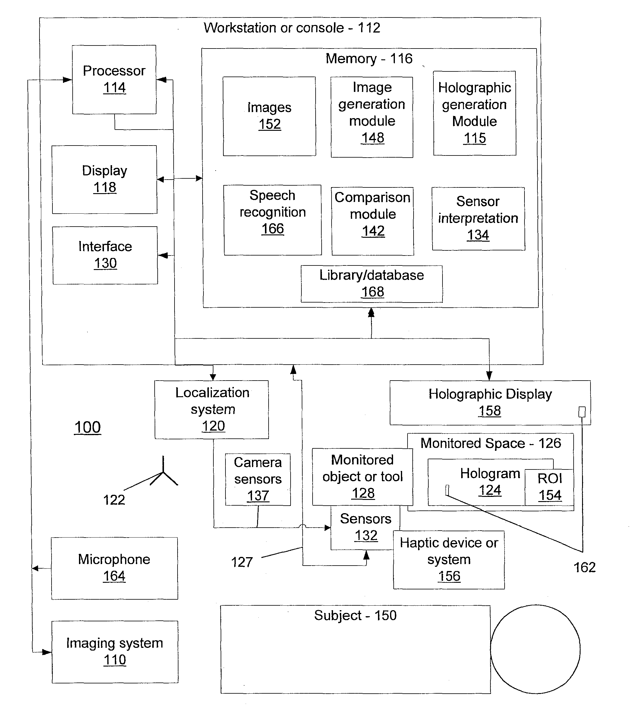
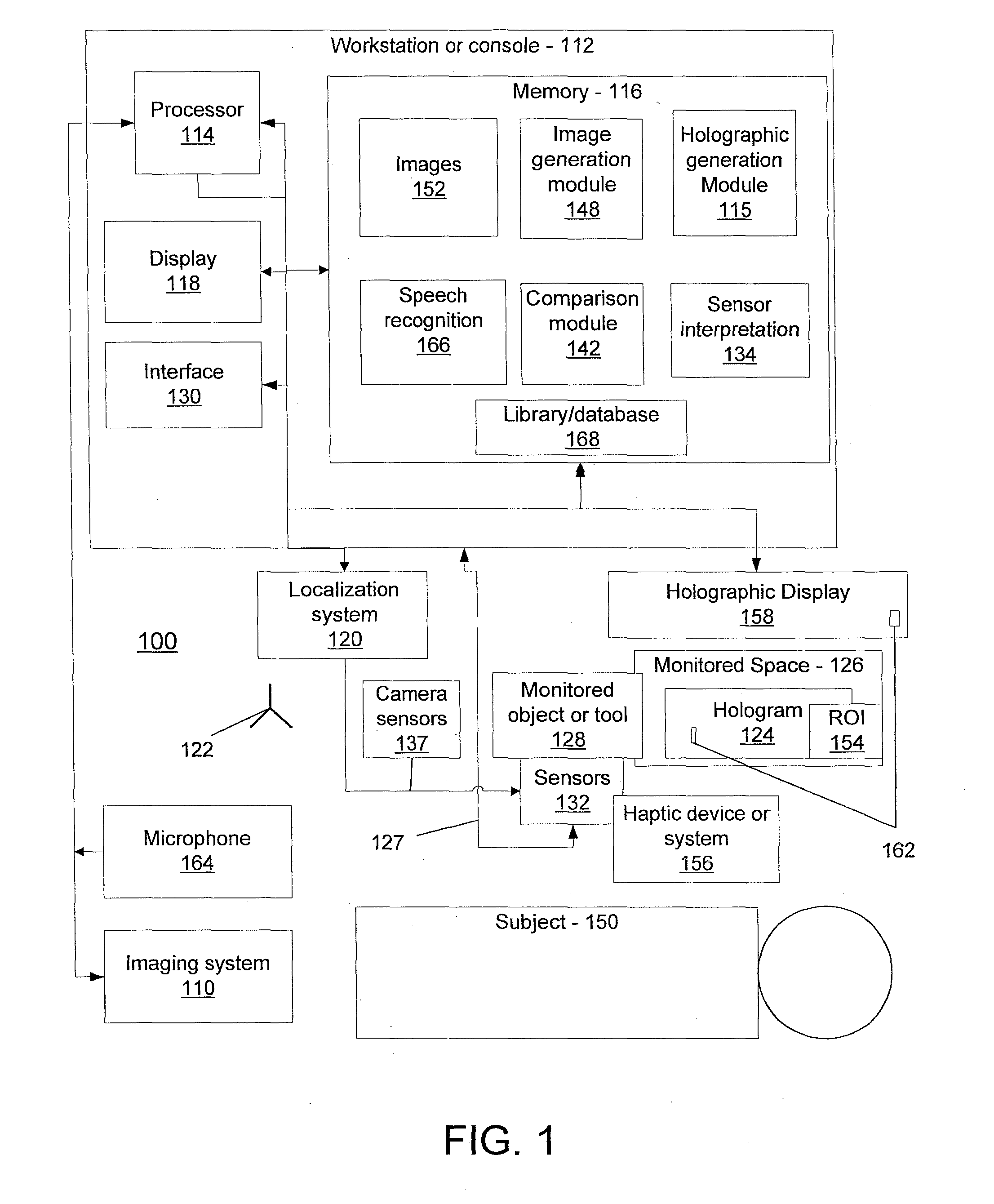
[0022]In accordance with the present principles, systems, devices and methods are described which leverage holographic display technology for medical procedures. This can be done using 3D holographic technologies (e.g., in-air holograms) and real-time 3D input sensing methods such as optical shape sensing to provide a greater degree of human-data interaction during a procedure. Employing holographic technology with other technologies potentially simplifies procedure workflow, instrument selection, and manipulation within the anatomy of interest. Such exemplary embodiments described herein can utilize 3D holographic displays for real-time visualization of volumetric datasets with exemplary localization methods for sensing movements in free space during a clinical procedure, thereby providing new methods of human-data interaction in the interventional suite.

[0023]In one exemplary embodiment, 3D holography may be used to fuse anatomical data with functional imaging and “sensing” inform...


PUM


Abstract

An interactive holographic display system includes a holographic generation module configured to display a holographically rendered anatomical image. A localization system is configured to define a monitored space on or around the holographically rendered anatomical image. One or more monitored objects have their position and orientation monitored by the localization system such that coincidence of spatial points between the monitored space and the one or more monitored objects triggers a response in the holographically rendered anatomical image.

Description

CROSS-REFERENCE TO RELATED APPLICATIONS[0001]This application claims priority to U.S. provisional application No. 61 / 549,273 filed on Oct. 20, 2011, the entire disclosure of which is hereby incorporated herein by reference in its entirety.BACKGROUND[0002]1. Technical Field[0003]The present disclosure relates to medical systems, devices and methods, and more particularly to systems, devices and methods pertaining to integration of holographic image data with other information to improve accuracy and effectiveness in medical applications.[0004]2. Description of the Related Art[0005]Auto-stereoscopic displays (ASDs) for three-dimensional (3D) visualization on a two-dimensional (2D) panel, without the need for user goggles / glasses, have been investigated. However, resolution and processing time limits the ability to render high quality images using this technology. Additionally, these displays have generally been confined to a 2D plane (e.g., preventing a physician from moving around or...

Claims


Application Information

Patent Timeline
Patent Type & Authority Applications(United States)
IPC IPC(8): G06T19/20G06F3/16A61B34/35A61B90/00
CPCG06T19/20G06T2219/2016G06F3/167G03H1/00G03H1/0005G03H1/2202G03H2001/0061G03H2210/33G03H2226/04A61B1/00G03H1/04
Inventor VERARD, LAURENTCHAN, RAYMONDRUIJTERS, DANIEL SIMON ANNADENISSEN, SANDER HANSSLEGT, SANDER
Owner KONINKLJIJKE PHILIPS NV
Learn More