Illumination device
A technology for lighting devices and circuit boards, applied in lighting devices, light sources, electrical components, etc., can solve problems such as electric shock, incomplete connection, and leakage of electricity for users, and achieve the effects of improving efficiency, reducing maintenance costs, and improving reliability
- Summary
- Abstract
- Description
- Claims
- Application Information
AI Technical Summary
Problems solved by technology
Method used
Image

Examples
no. 1 example
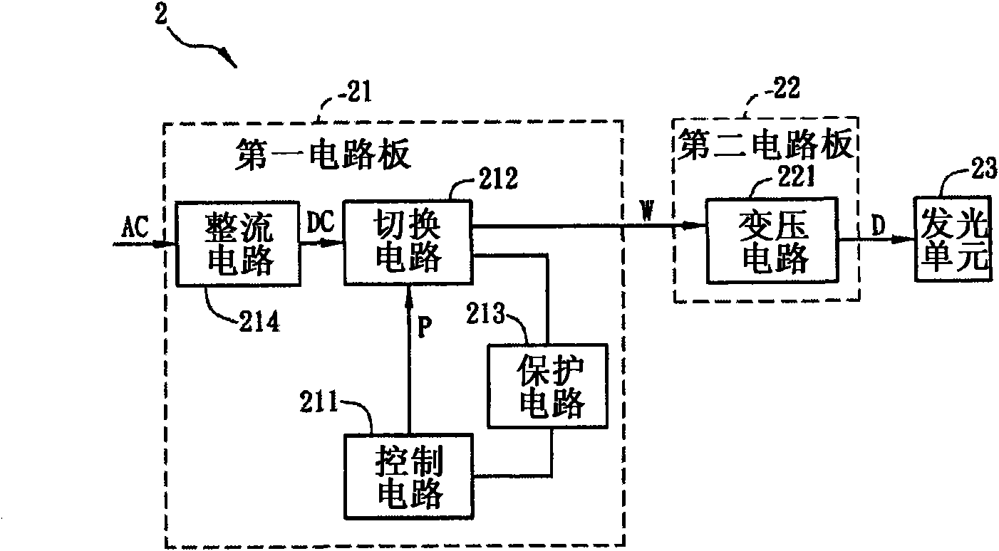
[0058] Please refer to figure 2 As shown, it is a block diagram of the lighting device 2 according to the first embodiment of the present invention. The lighting device 2 of this embodiment can be, for example, an indoor lighting device or an outdoor lighting device. board 21 , a second circuit board 22 and a light emitting unit 23 .
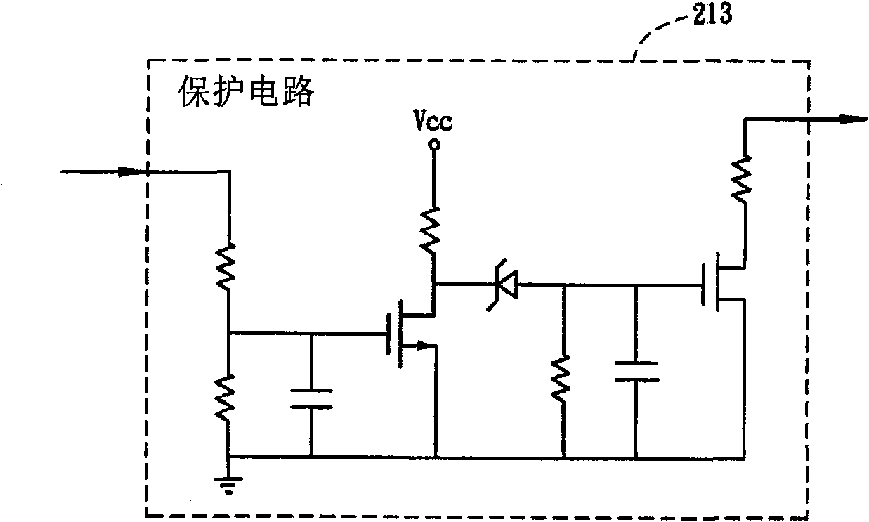
[0059] The first circuit board 21 has a control circuit 211 , a switch circuit 212 and a protection circuit 213 , and the control circuit 211 is electrically connected to the switch circuit 212 and the protection circuit 213 . Wherein, the switching circuit 212 may have a bipolar junction transistor (Bipolar Junction Transistor, BJT) and / or a field effect transistor (Field-Effect Transistor, FET), and the protection circuit 213 is, for example, a short circuit protection (Short Circuit Protection, SCP) circuit. In addition, in this embodiment, the first circuit board 21 also has a rectification circuit 214, however, this is not limitative. T...
no. 2 example
[0085] Please refer to Figure 9 As shown, it is a block diagram of the lighting device 3 according to the second embodiment of the present invention. The difference between the lighting device 3 and the lighting device 2 of the first embodiment is that the first circuit board 31 of the lighting device 3 only has a rectifier circuit 311 , while the second circuit board 32 has a control circuit 321 , a switching circuit 322 and a transformer circuit 323 , the three are electrically connected. The second circuit board 32 is also electrically connected to the first circuit board 31 , and the light emitting unit 33 is electrically connected to the transformer circuit 323 . In addition, in this embodiment, a plurality of second circuit boards 32 and a plurality of light emitting units 33 are taken as examples for illustration, but this is not intended to limit the present invention.
[0086]Therefore, the rectification circuit 311 generates a power signal DC according to the inpu...
no. 3 example
[0091] Please refer to Figure 10 As shown, it is a block diagram of the lighting device 4 according to the third embodiment of the present invention. The difference between the lighting device 4 and the lighting device 2 of the first embodiment is that: the first circuit board 41 of the lighting device 4 has a rectification circuit 411 and a control circuit 412 , which are electrically connected. The second circuit board 42 has a switch circuit 421 and a transformer circuit 422 , both of which are electrically connected. The second circuit board 42 is electrically connected to the first circuit board 41 , and the light emitting unit 43 is also electrically connected to the transformer circuit 422 .
[0092] Therefore, the rectification circuit 411 generates a power signal DC according to the input AC power signal AC, and the control circuit 412 generates at least one control signal P according to the power signal DC. The switching circuit 421 receives the power signal DC, a...
PUM
 Abstract
Description
Claims
Application Information
 - R&D Engineer
- R&D Manager
- IP Professional
- Industry Leading Data Capabilities
- Powerful AI technology
- Patent DNA Extraction
Browse by: Latest US Patents, China's latest patents, Technical Efficacy Thesaurus, Application Domain, Technology Topic.
© 2024 PatSnap. All rights reserved.Legal|Privacy policy|Modern Slavery Act Transparency Statement|Sitemap