ESO-based pure electric vehicle bus capacitor discharge system and method

A pure electric vehicle, bus capacitor technology, applied in the direction of electric vehicles, motor generator control, control system, etc., can solve the problems of bus voltage surge, slow discharge speed, damage to the power devices of the three-phase drive, etc., to avoid switching Tube breakdown, high discharge safety performance, and the effect of reducing the risk of electric shock

Active Publication Date: 2021-04-20
ZHEJIANG UNIV
View PDF3 Cites 2 Cited by
  • Summary
  • Abstract
  • Description
  • Claims
  • Application Information

AI Technical Summary

Problems solved by technology

[0003] Generally, in an emergency, the electric vehicle permanent magnet synchronous motor driver will turn off the power tube to prevent other problems, but this will cause the energy in the bus capacitor to be unable to be released, maintaining the bus voltage at a dangerously high level
So there are currently three main discharge strategies, one is to add a discharge circuit between the bus capacitor and the battery, but this will increase the cost and volume of the drive; the second is to short-circuit the three-phase drive, so that the energy is consumed in the three-phase drive On the power device, but the discharge current is uncontrollable in this way, which will damage the power device of the three-phase driver; there is another method that uses the permanent magnet synchronous motor winding as a discharge resistor to dissipate energy on the winding. This method has simple structure and low cost. Advantages such as low voltage and high reliability, but there may be problems of bus voltage surge and slow discharge speed

Method used


Image

  • ESO-based pure electric vehicle bus capacitor discharge system and method
  • ESO-based pure electric vehicle bus capacitor discharge system and method
  • ESO-based pure electric vehicle bus capacitor discharge system and method

Examples


Embodiment Construction

[0031]The technical solutions of the present invention will be described in detail with reference to the accompanying drawings and specific embodiments.

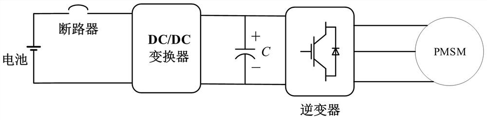
[0032]Such asfigure 1 As shown, in this implementation, ESO-based pure electric car busbar capacitance discharge system includes power cells, circuit breakers, DC / DC converters, busbar capacitors, inverters, permanent magnet synchronous motors and controllers; DC / DC The input side of the converter, the output side of the DC / DC converter and the bus capacitance, the inverter is connected in parallel; the inverter output side is connected three-phase permanent magnet synchronous motor; the circuit breaker is disposed in the power output of the power battery. Circuit;

[0033]The controller includes:

[0034]The first coordinate transformation module is used to acquire the three-phase current of the permanent magnet synchronous motor and the coordinate conversion, resulting in real-time measured D-axis current and Q-axis current;

[0035]T...


PUM


Abstract

The invention discloses an ESO-based pure electric vehicle bus capacitor discharging system and method. The system mainly comprises a controller, a power battery, a circuit breaker, a DC / DC converter, a bus capacitor, an inverter and a three-phase permanent magnet synchronous motor. According to the method, a permanent magnet synchronous motor winding is used as an energy bleeder. According to the method, a discharge process is divided into three stages: firstly, a fixed current is applied to a d axis in a weak magnetic voltage reduction stage, so that a bus voltage is rapidly reduced to a safe voltage, and the system enters a constant voltage stage; in the constant-voltage stage, ESO is adopted to observe the total loss in the system discharge stage, feedforward compensation is carried out, the bus voltage is stabilized at the safe voltage, and when the rotating speed is reduced to be lower than the safe rotating speed, the free deceleration stage is started, and d-axis and q-axis currents are gradually reduced to 0; through the above three stages, safe and rapid discharge of the bus capacitor of a pure electric vehicle driving system in emergency is realized, the surge phenomenon of the bus voltage is avoided, and the method has the advantages of high robustness and high safety.

Description

Technical field[0001]The present invention relates to a busbar capacitance discharge method, in particular to an ESO-based pure electric vehicle bus capacitance discharge system and method.Background technique[0002]Since the permanent magnet synchronous motor has high power density, high efficiency and simple control, it has gained more and more extensive applications in pure electric vehicle power drivers. The electric vehicle drive system mainly includes a motor, a motor driver, and a motor controller, wherein the motor driver further includes a three-phase inverter, a bidirectional DC / DC power converter, a busbar capacitor, and a circuit breaker between the battery and the capacitance. The bus capacitance in the drive has the function of wave and power exchange; during the driving of electric vehicles, when encountered a burst (for example, a car accident), the drive's circuit breaker will quickly move, cut off the connection between the battery and the drive to prevent Seconda...

Claims


Application Information

Patent Timeline
Patent Type & Authority Applications(China)
IPC IPC(8): H02J7/34H02P21/00H02P21/13H02P21/14H02P21/18H02P21/22H02P27/06H02M7/537H02M3/00H02M1/32H02H9/04H02P25/022
Inventor 杨家强张晓军杨昊林
Owner ZHEJIANG UNIV
Why Eureka
Try Eureka