Massage apparatus

A control device, disc technology, applied in the direction of roller massage, kneading massage equipment, massage auxiliary products, etc.

Inactive Publication Date: 2010-03-03
MATSUSHITA ELECTRIC WORKS LTD
View PDF1 Cites 7 Cited by
  • Summary
  • Abstract
  • Description
  • Claims
  • Application Information

AI Technical Summary

Problems solved by technology

In this case, it is difficult to apply heat to the peripheral parts of the massage head to apply warmth to the user's body

Method used


Image

  • Massage apparatus
  • Massage apparatus
  • Massage apparatus

Examples


Embodiment Construction

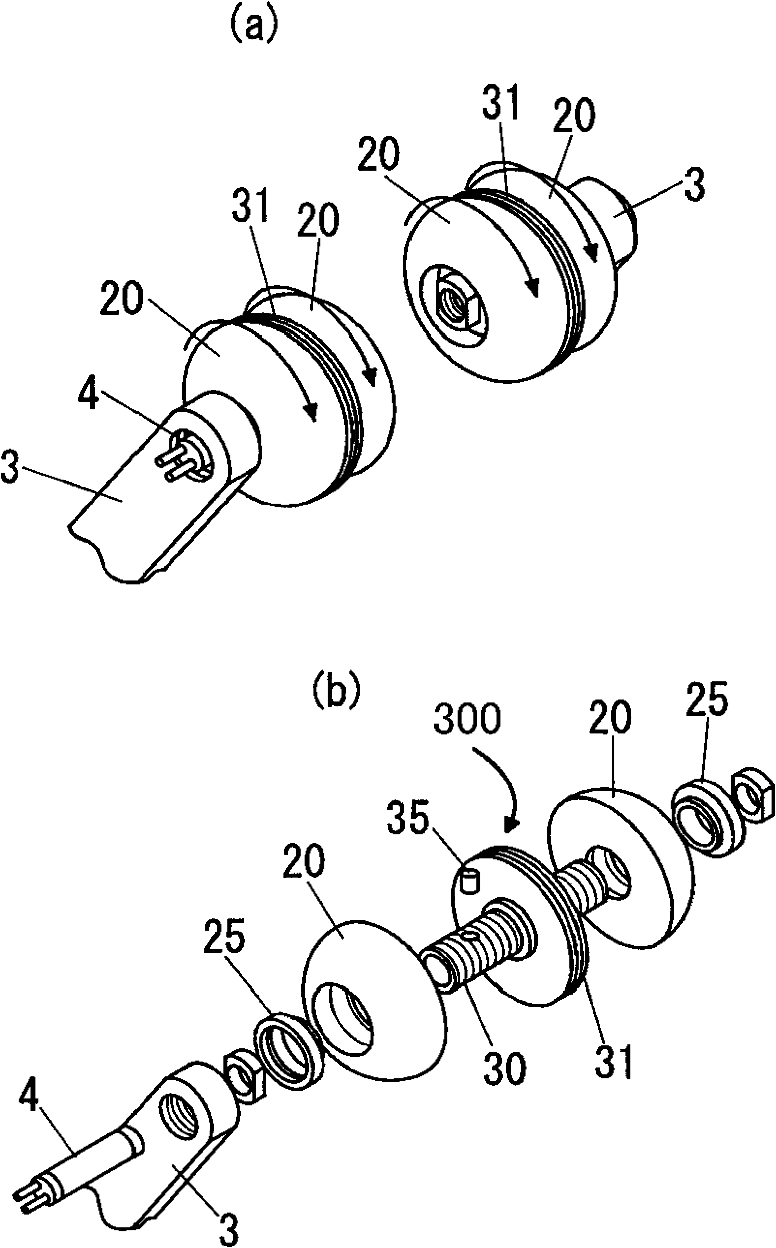
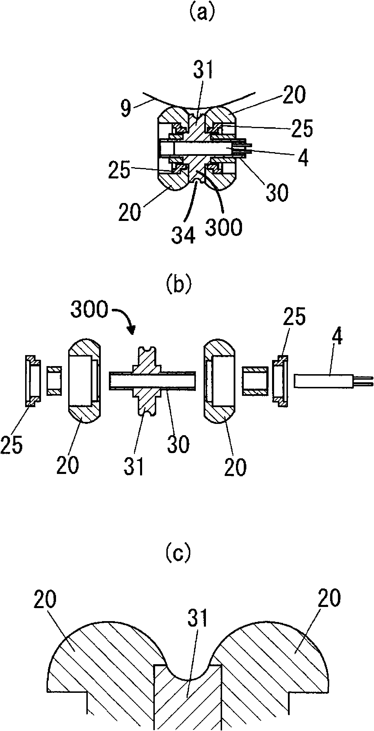
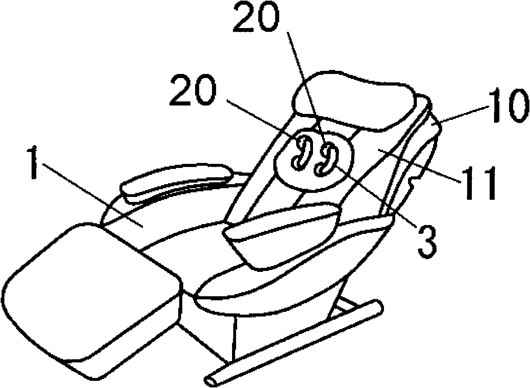
[0048] A massage device according to an embodiment of the present invention will be described with reference to the drawings. image 3 An external view of the massage device in this embodiment is shown. like Figure 1 to Figure 3 As shown, the massage device in this embodiment includes a seat 1 , a massage mechanism not shown, an arm 3 , a bracket 300 and a massage head 20 . The seat 1 has a backrest 10 . The seat 1 is configured to be able to recline. The massaging mechanism is configured to move up and down inside the backrest 10 . Arm 3 is coupled to the massage mechanism. The stand has a shaft 30 held by the end of the arm 3 . The massage head 20 is rotatably supported on the shaft 30 of the bracket 300 through the bearing 25 . The massage head 20 is made of elastic body.

[0049] The shaft 30 of the bracket 300 has a hollow central portion. The shaft 30 is made of a material such as aluminum, so the shaft 30 has strong thermal conductivity and high rigidity. The ...


PUM


Abstract

An arm (3) driven by a massage mechanism (A) is equipped with a carrier (300) having a shaft (30). The shaft (30) rotatably supports a therapeutic element (20). The carrier (300) has a heat source (4)therein and a disk (31) at the axial center. The carrier (300) or the therapeutic element (20) has a heat transmission means extending in radial direction from the carrier (300) to the outer peripheral surface of the therapeutic element (20). Consequently, a heat by which a human body can feel warmth can be effectively given to the outer peripheral part of the therapeutic element and the outer peripheral part of the disk (31) of the carrier(300) by the heat transmission means.

Description

technical field [0001] The invention relates to a massage device, which is configured to massage a human body through a massage head. Background technique [0002] Japanese Patent Application Publication No. 2005-102919 discloses a conventional massage device. The massage device controls the massage head to massage the user's back. The massage head is arranged, for example, on the seat back. The massage head is configured to apply pressure to the user's back through a cover provided at the front of the backrest. [0003] When the masseur massages the person receiving the massage, the temperature of the masseur's hands is transmitted to the person receiving the massage. Therefore, the massage therapist can make people feel comfortable while giving massage. However, the massage heads of the massage device are at most room temperature. For this purpose, a heat source is assembled in the massage head. The massage head with heat source can give people warmth and compression...

Claims


Application Information

Patent Timeline
Patent Type & Authority Applications(China)
IPC IPC(8): A61H7/00
CPCA61H2015/0028A61H2201/0149A61H15/00A61H2201/0207A61H2205/081A61H2201/1669A61H2201/5082A61H2201/0138A61H2201/0228A61H7/00
Inventor 长野正树汤川隆志中村润二小川哲史
Owner MATSUSHITA ELECTRIC WORKS LTD
Why Eureka
Try Eureka