
Massager

A technology of massager and vibrator, which is applied in the direction of vibration massage, massage auxiliary products, equipment for compressing reflection points, etc. It can solve the problems of poor massage effect and achieve effective massage effect

Inactive Publication Date: 2004-05-19
KAWASAKI SEIKI MFG CORP
View PDF1 Cites 4 Cited by
  • Summary
  • Abstract
  • Description
  • Claims
  • Application Information

AI Technical Summary

Problems solved by technology

[0003] However, in the above-mentioned prior art, the vibration of the massager is fixed, and the most appropriate vibration cannot be adjusted according to the massage site, so there is a problem that the massage effect is not good.

Method used


Image

  • Massager
  • Massager
  • Massager

Examples


Embodiment Construction

[0018] Hereinafter, the present invention will be described in detail according to specific embodiments.

[0019] figure 1 Shown is a schematic front view of the massager 1 according to the embodiment of the invention. The massager 1 is constituted by combining the vibrator 2 and the battery mounting part 3 into a combined part 4, and has a generally cylindrical shape as a whole.

[0020] The battery mounting part 3 is provided with a power switch part 5, so that through the switch part 5, the switch of the power source and the selection of the vibration level can be controlled at the same time. That is, turning off the power is performed at the position of level 0, and the selection of the vibration level is performed by sliding to switch the positions of the adjusted vibration levels 1-3.

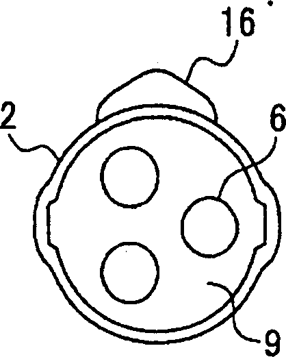
[0021] figure 2 Shown is a schematic top view of the massager 1 . The end portion of the vibrator 2 side of the massager 1 is provided with a head 9, and it is preferable to make, fo...


PUM


Abstract

A massager capable of adjusting its vibration by conotrol the rotaion of its motor. To solve the problem in the conventional massager in which the vibration of the massager is adjusted by controlling the rotational speed of a motor. This massager obtains vibration by rotating an eccentric weight arranged at the shaft of the motor by rotating the motor by supplying power source. At the switch part of the power source, a slide coil obtained by winding a metallic wire in the state of a coil and a slidable brush in contact with the slide coil are arranged. By sliding the brush, a position in contact with the slide coil is varied so as to control the rotational speed of the motor. Thus, the rotational speed of the motor is controlled to adjust the vibration of the massager.

Description

technical field [0001] The invention relates to a massager capable of adjusting vibration by controlling the rotation of a motor. Background technique [0002] Hitherto, as this kind of massager, there is, for example, one that generates vibrations by rotating an eccentric mass mounted on a motor shaft and uses the vibrations to perform massage (refer to Japanese Patent Application Laid-Open No. 7-299151 (page 2) ). [0003] However, in the above-mentioned prior art, the vibration of the massager is fixed, and the most appropriate vibration cannot be obtained by adjusting according to the massage site, so there is a problem that the massage effect is not good. [0004] Therefore, the problem that must be solved in the existing massager is: control the rotation speed of the motor so that the vibration of the massager can be adjusted. Contents of the invention [0005] The purpose of the present invention is proposed in order to solve this problem. [0006] As a specific ...

Claims


Application Information

Patent Timeline
Patent Type & Authority Applications(China)
IPC IPC(8): A61H23/02
CPCA61H23/0263
Inventor 藤泽弘
Owner KAWASAKI SEIKI MFG CORP
Learn More