Ultrahigh-speed embroidery machine head

An embroidery machine, ultra-high-speed technology, applied in the field of embroidery machines, can solve the problems of complicated maintenance process, rising material cost, low efficiency, etc., and achieve the effects of stable power transmission, small driving force loss, and low vibration and noise.

Pending Publication Date: 2017-06-09
诸暨市驰龙科技有限公司
View PDF9 Cites 4 Cited by
  • Summary
  • Abstract
  • Description
  • Claims
  • Application Information

AI Technical Summary

Problems solved by technology

Although this structure can offset part of the vibration caused by centrifugal force, the structure of the needle bar cam will inevitably change when the counterweight is added. In order to connect with the counterweight, the structure of the needle bar cam is more complicated, which undoubtedly increases the material cost and processing cost
At the same time, increasing the counterweight in the axial direction of the main shaft will inevitably increase the width of the original machine head casing, which will also lead to an increase in material costs
The above-mentioned mating structure will not only lead to an increase in cost, but because the counterweight and the needle bar cam are connected by bolts, the bolts may become loose under long-term high-speed rotation, which will break the internal balance. Therefore, regular maintenance of the counterweight is required In the maintenance process, the casing needs to be opened, and the maintenance process is complicated. At the same time, after adjusting the counterweight, it is necessary to re-adjust the centrifugal force of the head system. This kind of maintenance process is complicated and inefficient.

Method used


Image

  • Ultrahigh-speed embroidery machine head
  • Ultrahigh-speed embroidery machine head
  • Ultrahigh-speed embroidery machine head

Examples


Embodiment Construction

[0038] In order to make the object, technical solution and advantages of the present invention clearer, the present invention will be further described in detail below in conjunction with the accompanying drawings and embodiments. It should be understood that the specific embodiments described here are only used to explain the present invention, not to limit the present invention.

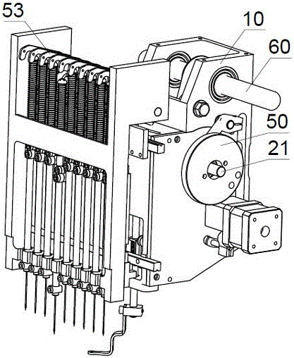
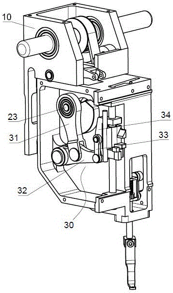
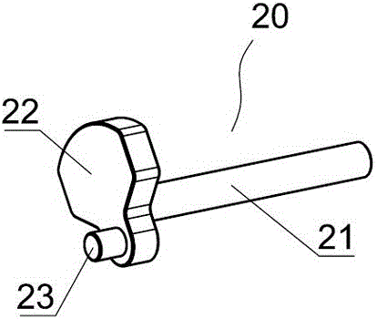
[0039] Such as figure 1 , 2 , 6, and 7, the casing 10 in the head of the ultra-high-speed embroidery machine of this embodiment includes a left chamber 11 and a right chamber 12, and a partition 13 is arranged between the left chamber 11 and the right chamber 12, and the partition The plate 13 is provided with a spindle connection hole 131 . The sides of the left chamber 11 and the right chamber 12 away from the partition 13 are respectively provided with a left cover plate (not shown in the figure) and a right cover plate 14 . In this embodiment, one end of the main shaft 21 protrudes from the ...


PUM


Abstract

The invention relates to the technical field of embroidery machines, and particularly discloses an ultrahigh-speed embroidery machine head. The ultrahigh-speed embroidery machine head is characterized in that a case is provided with a left chamber and a right chamber, a dynamic balance cam, a presser foot cam and a take-up-lever cam are positioned in regions on the outer sides of the left chamber, the right chamber and a right cover plate, a spindle between the dynamic balance cam and the presser foot cam is rotationally movably connected with a partition plate, and the presser foot cam and the take-up-lever cam are rotationally movably connected with the right cover plate. The ultrahigh-speed embroidery machine head has the advantages that the dynamic balance cam, the presser foot cam and the take-up-lever cam are isolated in the three regions by the partition plate and the right cover plate, every two adjacent regions are connected with each other by the spindle and the case in a supported manner, and accordingly resonance effects due to centrifugal force generated by various components can be prevented; the dynamic balance cam is integrally formed by a balance block and an eccentric column, the eccentric column can drive needle bars to move via a needle bar driving connecting rod assembly, centrifugal force generated by the balance block is used for offsetting the centrifugal force generated by the other components, accordingly, vibration can be eliminated, and the spindle can rotate at the high speeds.

Description

technical field [0001] The invention relates to the technical field of embroidery machines, in particular to an ultra-high-speed embroidery machine head. Background technique [0002] The embroidery machine head in the prior art usually includes a needle bar cam, a presser foot cam and a thread take-up cam arranged coaxially. The needle bar cam, the presser foot cam and the thread take-up cam are eccentric cams. During the rotation of the main shaft, Due to the effect of inertia, it will inevitably cause the machine head to vibrate, which not only produces noise but also affects the life of the machine head and the embroidery thread breakage rate. Especially when the speed is higher, the vibration will become more obvious. The existing structure of the machine head Restricted the development of high-speed machines. [0003] The Chinese utility model patent with the notification number CN203834159U discloses a dynamic balancing device for the needle bar cam mechanism of a co...

Claims


Application Information

Patent Timeline
Patent Type & Authority Applications(China)
IPC IPC(8): D05C13/00D05C11/06D05C9/20
CPCD05C9/20D05C11/06D05C13/00
Inventor 何贵友杨晓理
Owner 诸暨市驰龙科技有限公司
Why Eureka
Try Eureka