Safe cutting machine

A cutting machine and safe technology, applied in the cutting machine field, can solve the problem that the cutting machine is not suitable for cutting standard circular arcs, etc., and achieve the effects of light weight, safe and flexible operation, and simple structure

Inactive Publication Date: 2012-08-01
付志洪 +1
View PDF6 Cites 0 Cited by
  • Summary
  • Abstract
  • Description
  • Claims
  • Application Information

AI Technical Summary

Problems solved by technology

[0003] The purpose of the present invention is to solve the problem that existing cutting machines are not suitable for cutting standard circular arcs, and to provide a safe cutting machine

Method used


Image

  • Safe cutting machine
  • Safe cutting machine
  • Safe cutting machine

Examples


Embodiment Construction

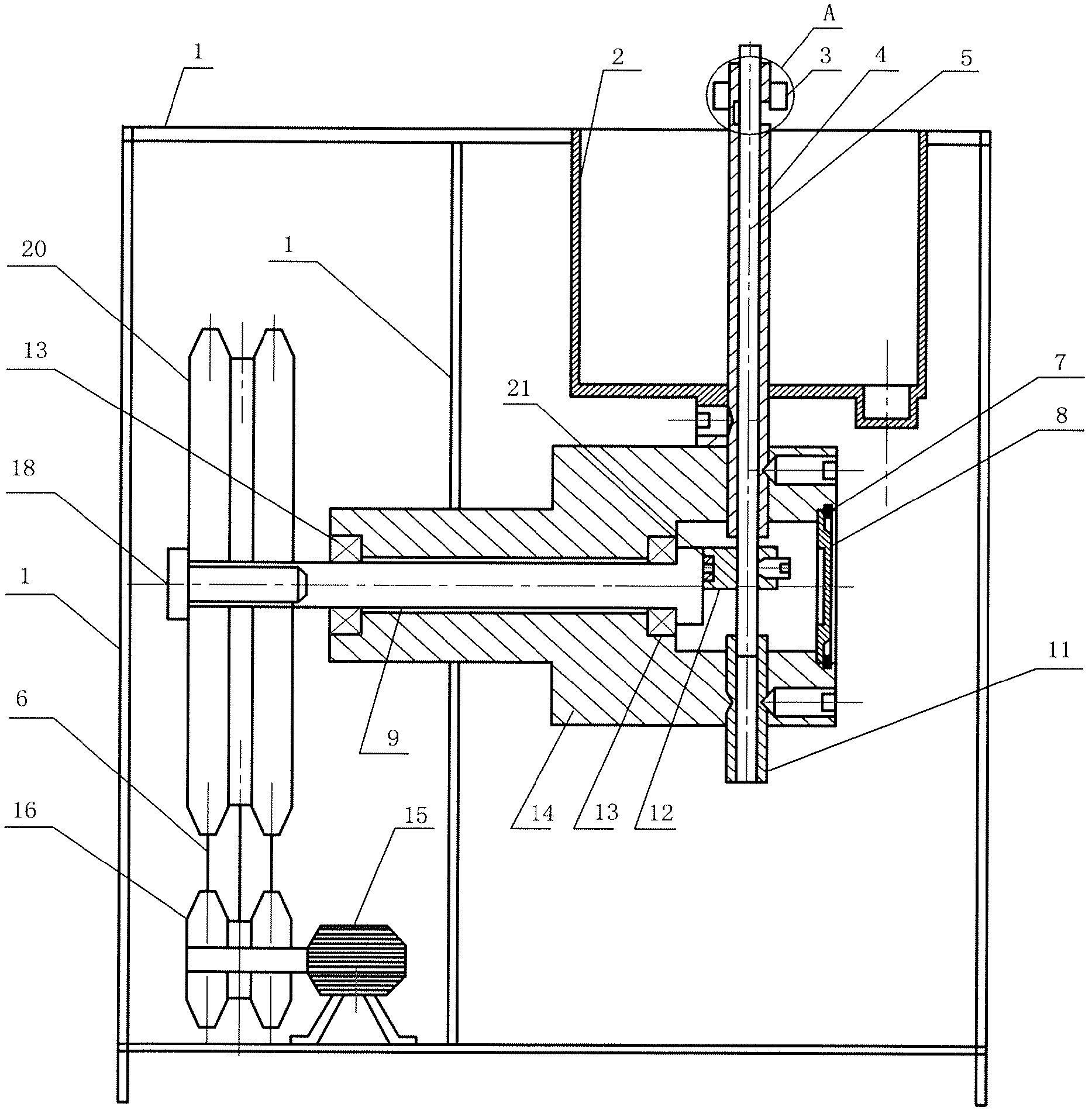
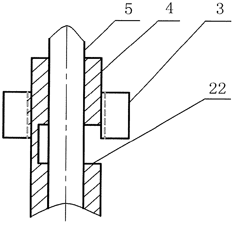
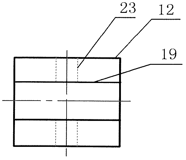
[0023] Such as figure 1 As shown, the safety cutting machine of the present invention includes: a frame 1, a transmission mechanism, a fuselage 14, a shaft 9, a cutter bar 5 and a machine cover 8, and the fuselage 14 is fixed on the frame 1 by screws (not shown) , the shaft 9 is horizontally mounted on the fuselage 14, and a pair of bearings 13 are mounted on the shaft 9, and the bearings 13 are installed in the fuselage 14. One end of the shaft 9 stretches out from the fuselage 14, and the transmission mechanism drives it to rotate. The transmission mechanism includes: a motor 15, a small pulley 16, a large pulley 20 and a belt 6, and the large pulley 20 is fixed on the shaft 9 by a safety screw 18. Belt 6 is contained on small pulley 16 and large pulley 20, and motor 15 is fixed on the frame 1, and motor 15 drives small pulley 16 rotations, and belt 6 drives large pulley 20 rotations, and large pulley 20 drives shaft 9 rotations. The machine cover 8 is fixed on the fuselage...


PUM


Abstract

A safe cutting machine comprises a frame, a transmission mechanism, a body, a shaft and a cutter bar, wherein the body is fixed on the frame, the shaft is mounted on the body transversely, one end of the shaft extends out of the body and is driven to rotate by the transmission mechanism, the cutter bar is mounted on the body vertically, a directional chute and a rectangular sliding piece are further mounted in the body, an eccentric block is disposed on the other end of the shaft, the eccentric block is away from the axis of the shaft, the sliding piece is sleeved on the eccentric block, the directional chute is sleeved outside the sliding piece, a vertical cutter bar hole is reserved in the directional chute, and the cutter bar penetrates through the cutter bar hole and is fixed on the directional chute vertically. The safe cutting machine is simple in structure, small in size, light in weight, safe and flexible in operation, time-saving, labor-saving and the like. In addition, functions of waste material collecting, vibration of the cutter bar reducing and noise reducing are provided, so that the safe cutting machine is especially suitable for machining inner and outer standard circular thin plates of various standards and various curved thin plates, and is an ideal tool for metal plate industry, machine maintenance industry and the like.

Description

technical field [0001] The invention relates to a cutting machine, in particular to a safety cutting machine for cutting metal sheets. Background technique [0002] Existing equipment for sheet metal cutting and processing is divided into two categories, one is a punching type linear shearing machine; the other is a vibration type curved shearing machine, and they are all suitable for mass production. The cost of the above two types of equipment is high and consumes electric energy, so it is used in small batch production or repair industries. Iron scissors are mostly used in the shearing process of plates, and manual cutting with iron scissors has low efficiency, poor quality, time-consuming and laborious. Contents of the invention [0003] The purpose of the present invention is to solve the problem that existing cutting machines are not suitable for cutting standard circular arcs, and provide a safe cutting machine. [0004] In order to accomplish the purpose of the i...

Claims


Application Information

Patent Timeline
IPC IPC(8): B23D15/08B23D33/00
Inventor 付志洪俞忠全
Owner 付志洪
Why Eureka
Try Eureka