
T-MPLS device model and layering encapsulating method

A technology of T-MPLS and equipment model, applied in the direction of selection device, selection device of multiplexing system, transmission system, etc., can solve the problems of no equipment model architecture and hierarchical packaging method, etc., and achieve the effect of clear hierarchical structure

Active Publication Date: 2010-03-10
FENGHUO COMM SCI & TECH CO LTD
View PDF0 Cites 8 Cited by
  • Summary
  • Abstract
  • Description
  • Claims
  • Application Information

AI Technical Summary

Problems solved by technology

However, there is no standard device model architecture and hierarchical encapsulation method for T-MPLS technology at present

Method used


Image

  • T-MPLS device model and layering encapsulating method
  • T-MPLS device model and layering encapsulating method
  • T-MPLS device model and layering encapsulating method

Examples


Embodiment Construction

[0041] The present invention will be described in further detail below in conjunction with the accompanying drawings.

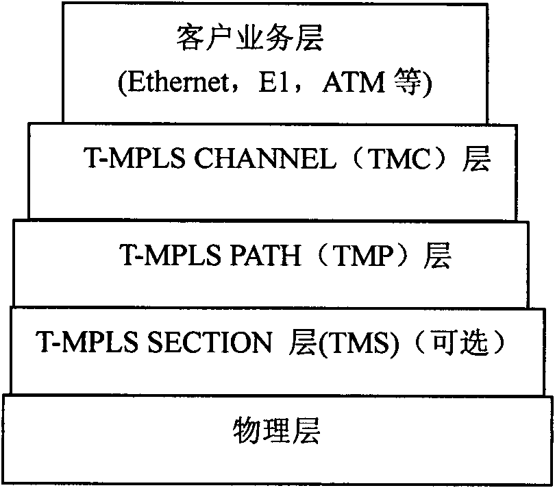
[0042] One of the purposes of the present invention is to realize the hierarchical service encapsulation function, figure 1 Shown is the service encapsulation model based on T-MPLS, which is divided into customer service layer, TMC (T-MPLS Channel) layer, TMP (T-MPLS Path) layer, TMS (T-MPLS Section) layer and physical layer. User business first enters the customer service layer, then is encapsulated into the TMC label, enters the TMC layer, and then is encapsulated into the TMP label, enters the TMP layer, then enters the TMS layer, and finally is sent to the physical layer. The packaging at each level adopts the prior art.

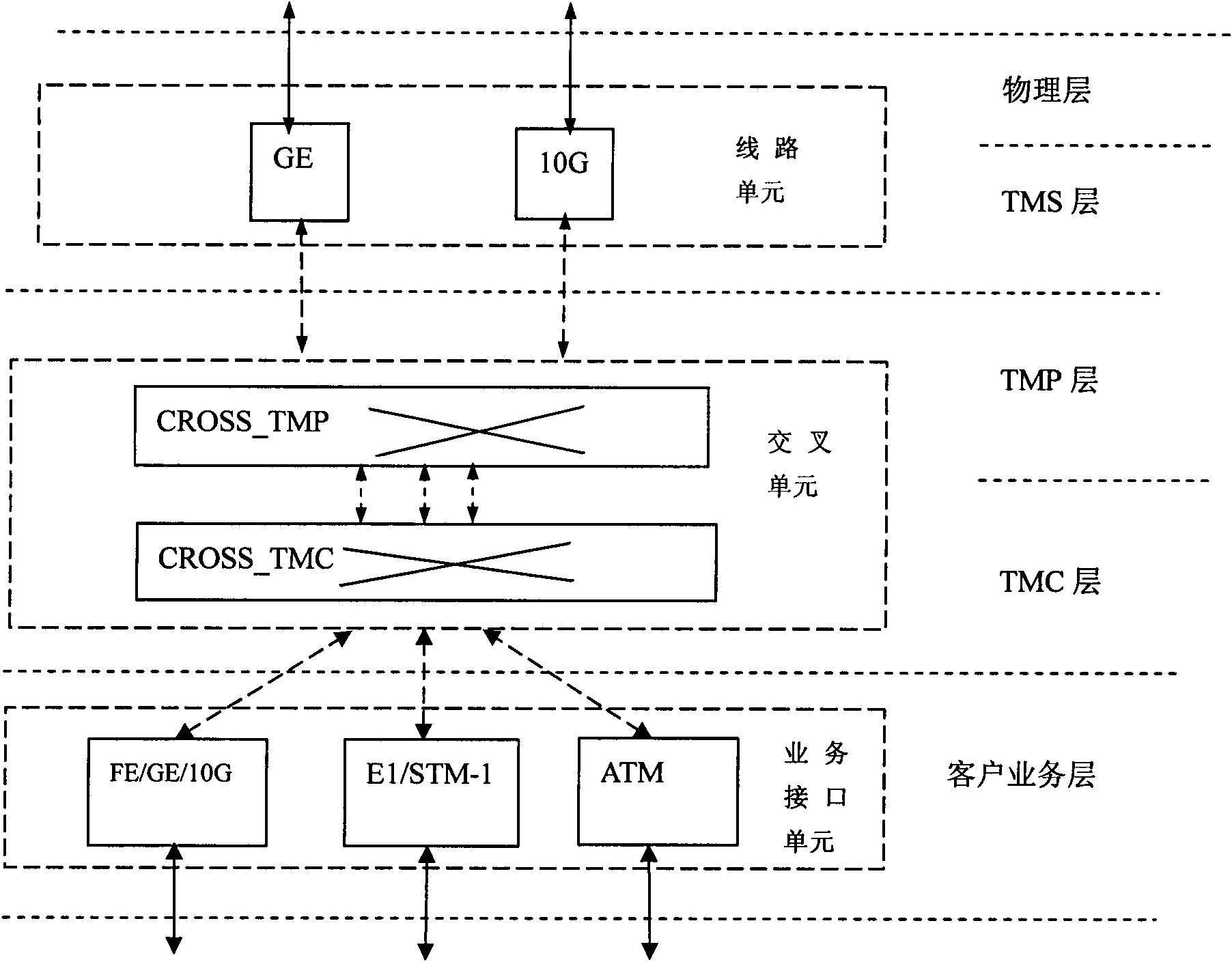
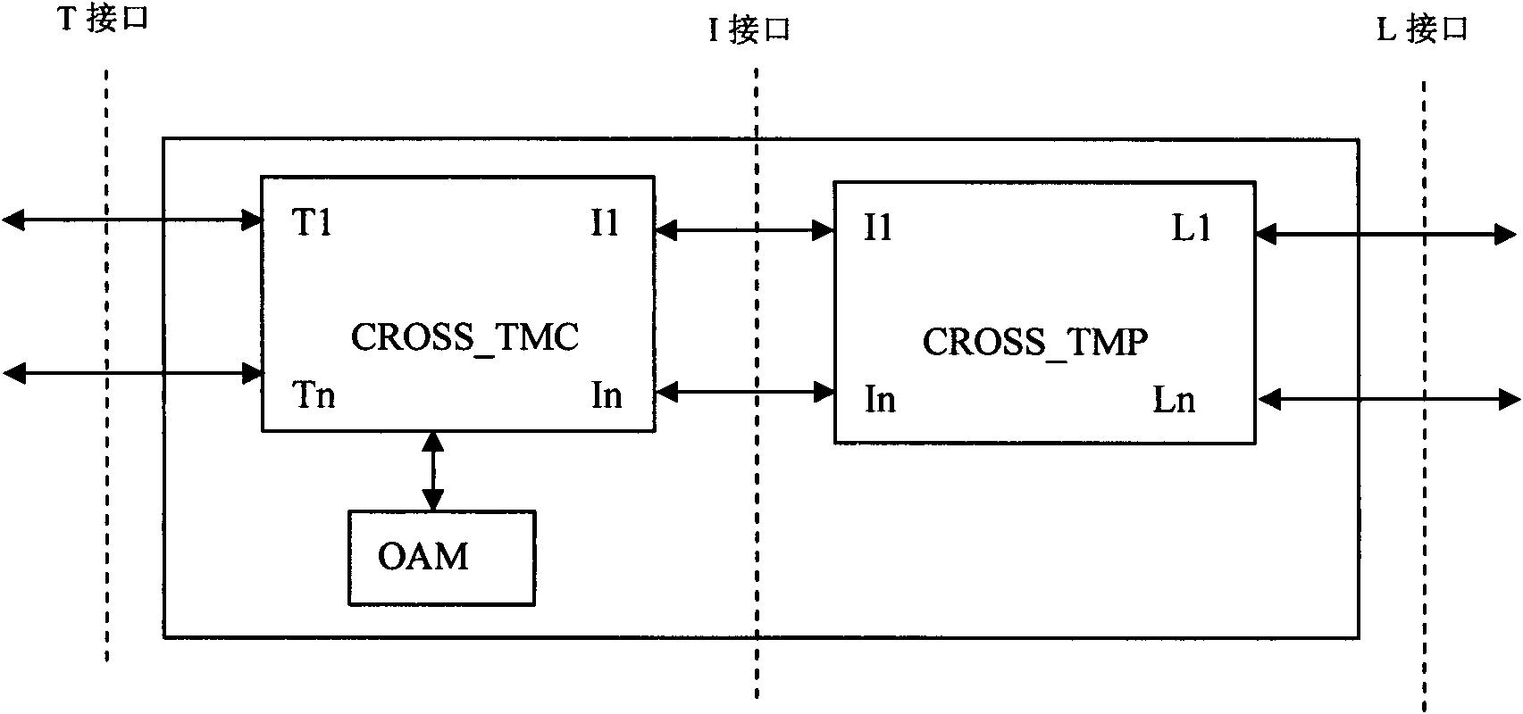
[0043] According to the concept of hierarchy, the present invention provides figure 2 The T-MPLS equipment model includes service interface unit, cross unit and line unit, and the cross unit includes two parts: CROSS_TMC and CROSS_TM...


PUM


Abstract

The invention provides a T-MPLS device model and a layering encapsulating method, wherein, the device model comprises a business interface unit which is used for accessing and encapsulating varied businesses in different TMCs and sending the businesses to a cross unit in a convergent manner; the cross unit is used for encapsulating various different TMC businesses from the business interface unitinto different TMPs and then forwarding a business package with two layers of labels to different line units, and meanwhile is in charge of protection switching of varied businesses, generation and finalization of an OAM packet on a TMC layer and OAM on a TMP layer; and the line units are used for forwarding a data packet with the two layers of labels sent from the cross unit to a T-MPLS network,and meanwhile are in charge of generation and finalization of the OAM on a TMS layer. The invention has a clear layered architecture, can help easily realize varied layering functions and varied protection functions, and perform add / drop multiplexing on the businesses in a non-blocking manner, thus meeting the T-MPLS standard requirement.

Description

technical field [0001] The invention relates to T-MPLS technology, specifically a T-MPLS equipment model and a hierarchical encapsulation method. Background technique [0002] Packet Transport Network (PTN) technology is the inevitable product of the development of optical transport equipment under the promotion of IP-based telecommunication services. It is designed for the bursty and statistical multiplexing transmission requirements of packet traffic. PTN technology has technical characteristics such as connection-oriented data forwarding mechanism, multi-service bearer, strong network scalability, rich OAM, strict QoS mechanism, and 50ms network protection. [0003] The mainstream technical solutions of PTN can be divided into two categories: Ethernet enhancement technology and transmission technology combined with MPLS (multi-protocol label switching). The former is represented by PBB-TE (carrier backbone network bridging transmission technology), and the latter is repr...

Claims


Application Information

Patent Timeline
IPC IPC(8): H04L12/56H04J3/08H04Q11/00H04L45/50H04L47/43
Inventor 江榕徐剑辉周志强陈晓武涂育红施先清柳光权杨政权
Owner FENGHUO COMM SCI & TECH CO LTD
Learn More