Supercharge Your Innovation With Domain-Expert AI Agents!

Oil scavenger for gas-oil separator of engine

A technology for oil and gas separators and engines, which is applied to engine components, machines/engines, mechanical equipment, etc., can solve the problems of backward oil absorption and discount of oil and gas separation effect, and achieve the effect of preventing backward oil absorption, ensuring the effect of oil and gas separation, and having a simple structure.

Active Publication Date: 2010-03-17
CHERY COMML VEHICLE ANHUI
View PDF0 Cites 3 Cited by
  • Summary
  • Abstract
  • Description
  • Claims
  • Application Information

AI Technical Summary

Problems solved by technology

Regardless of the type of oil-gas separator, the oil return effect plays an important role in the oil-gas separation efficiency. Once the pressure in the upper part of the oil return hole is lower than the pressure in the lower part, the oil will be sucked back and the effect of oil-gas separation will be greatly reduced.

Method used


Image

  • Oil scavenger for gas-oil separator of engine
  • Oil scavenger for gas-oil separator of engine

Examples


Embodiment 1

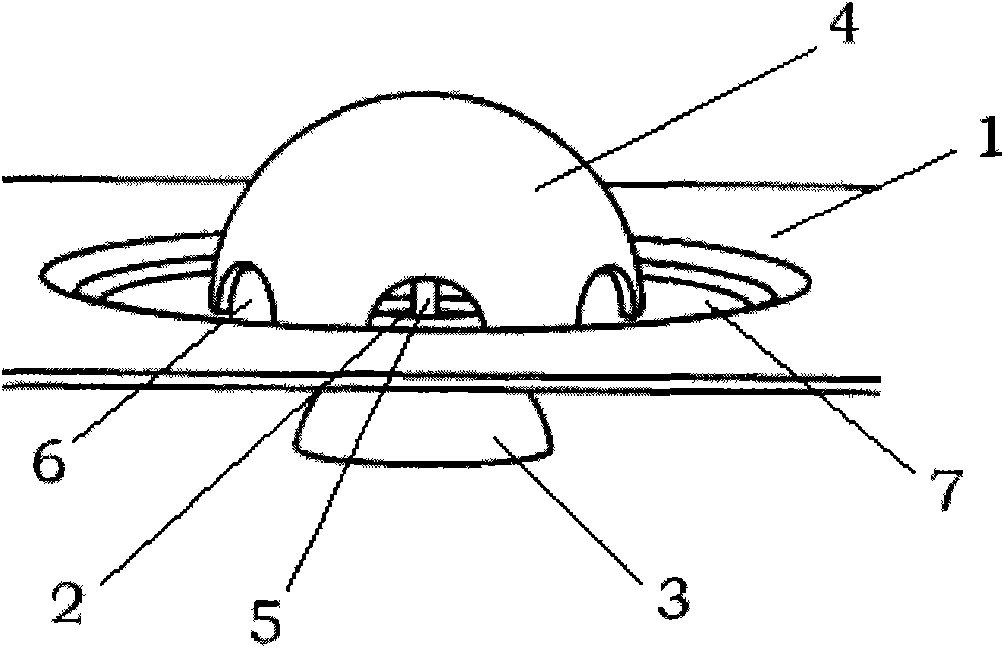
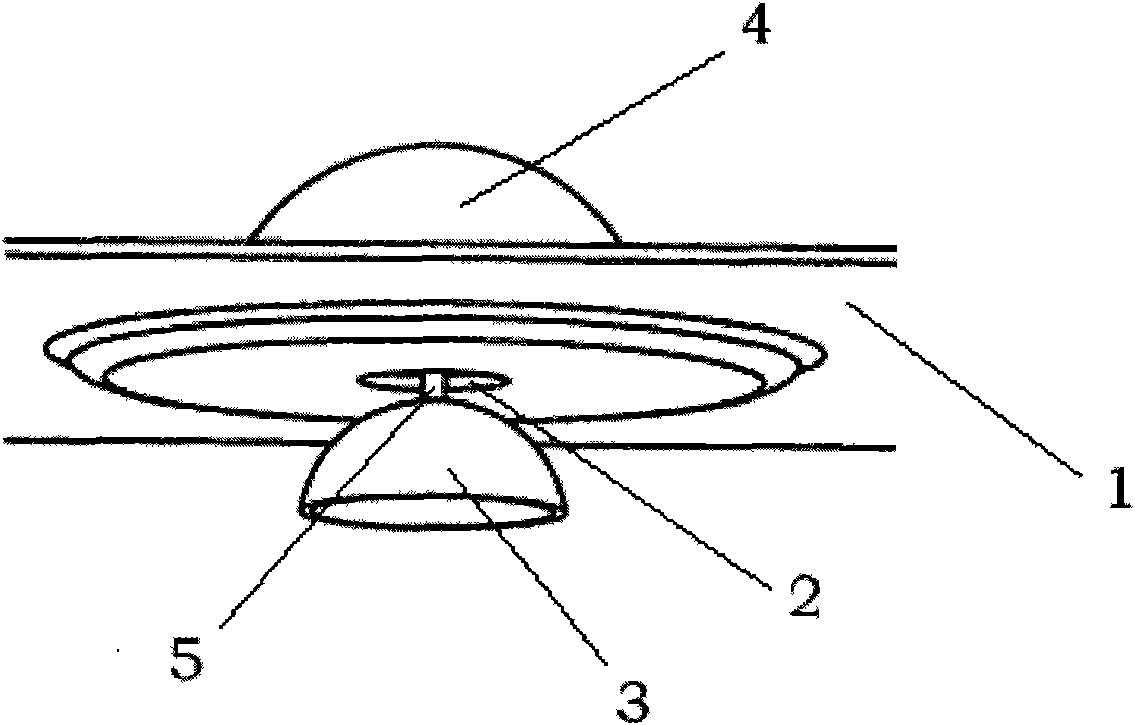
[0017] Such as figure 1 , 2 As shown, the oil return device of the engine oil-gas separator of the present embodiment includes a flat plate 1 for separating the intake manifold and the crankcase, and the flat plate 1 is provided with a circular oil return hole 2, and the oil return The bottom of the hole 2 is provided with a self-closing valve 3 that can automatically block the oil return hole 2 under the action of the upward airflow of the crankcase. The self-closing valve 3 is umbrella-shaped, installed at the bottom of the oil return hole 2 and can Moving up and down along the axis of the oil return hole, the diameter of the oil return hole 2 is smaller than the diameter of the bottom of the self-closing valve 3 . The top of the self-closing valve 3 is fixedly connected with an umbrella-shaped booster component 4 through a threaded rod 5 , the bottom of the booster component 4 has an oil return gap 6 , and the booster component 4 is located above the oil return hole 2 .

...


PUM


Abstract

The invention provides an oil scavenger for a gas-oil separator of an engine for preventing oil suck-back phenomena. The oil scavenger comprises a slab for separating an induction manifold from a crankcase. A circular oil return hole is disposed on the slab. A self-closing valve which is disposed under the oil return hole can automatically plug up the oil return hole under the action of the upwardairflow of the crankcase. When gas and oil are normally separated, the self-closing valve is under the oil return hole with a clearance and the separated oil turns back to the crankcase from the oilreturn hole. When suck-back phenomena is caused by the higher pressure in the crankcase of engine than the pressure in the induction manifold, the suck-back airflow will drive the self-closing valve to move upward for plugging up the oil return hole and efficiently preventing the suck-back phenomena. The oil scavenger of the invention has the advantages of simple structure, low cost, easy manufacture and installation, and better oil scavenging effect. The oil scavenger further can efficiently prevent the suck-back phenomena to ensure the gas-oil separating effect of the gas-oil separator.

Description

technical field [0001] The invention belongs to the technical field of engines, and in particular relates to an oil-gas separator of an engine crankcase ventilation system. Background technique [0002] In order to prevent the oil and gas in the engine crankcase from escaping into the atmosphere and causing the oil to deteriorate, the engine must be equipped with an oil and gas separator. At present, there are many kinds of oil and gas separators in engines, such as labyrinth type, cyclone type, filter type, etc. These oil and gas separators are often arranged in the engine valve chamber cover or outside the valve chamber cover, and then in the valve chamber cover or An oil return hole is arranged outside to allow the oil separated by the oil-air separator to flow back into the crankcase of the engine, while the gas enters the engine through the intake manifold. Regardless of the type of oil-gas separator, the oil return effect plays an important role in the oil-gas separat...

Claims


Application Information

Patent Timeline
IPC IPC(8): F01M13/04
Inventor 张侠
Owner CHERY COMML VEHICLE ANHUI
Features
  • R&D
  • Intellectual Property
  • Life Sciences
  • Materials
  • Tech Scout
  • Unparalleled Data Quality
  • Higher Quality Content
  • 60% Fewer Hallucinations
Learn More