Lens regulation module

A technology for adjusting modules and lenses, applied in installation, optics, instruments, etc., can solve problems such as image out-of-focus, failure to meet different needs of projector space planning, large cumulative tolerance, etc., and achieve the effect of reducing cumulative tolerance

Inactive Publication Date: 2010-03-17
CORETRONIC
View PDF0 Cites 2 Cited by
  • Summary
  • Abstract
  • Description
  • Claims
  • Application Information

AI Technical Summary

Problems solved by technology

However, the configuration of these components of the lens adjustment module 100 cannot meet the different requirements of other designers for the space planning inside the projector.
[0006] In addition, since the guide rods 130 and 150 and the first adjustment bracket 140 are all disposed between the base 120 and the second adjustment bracket 160 , after the lens adjustment module 100 is assembled, the gap between the second adjustment bracket 160 and the base 120 The cumulative tolerance (cumulative tolerance) is larger
Therefore, the predetermined interval between the second adjustment bracket 160 and the base 120 will be affected by the above-mentioned cumulative tolerance, so that the image projected by the lens 170 configured on the second adjustment bracket 160 will be out of focus.

Method used


Image

  • Lens regulation module
  • Lens regulation module
  • Lens regulation module

Examples


no. 1 example

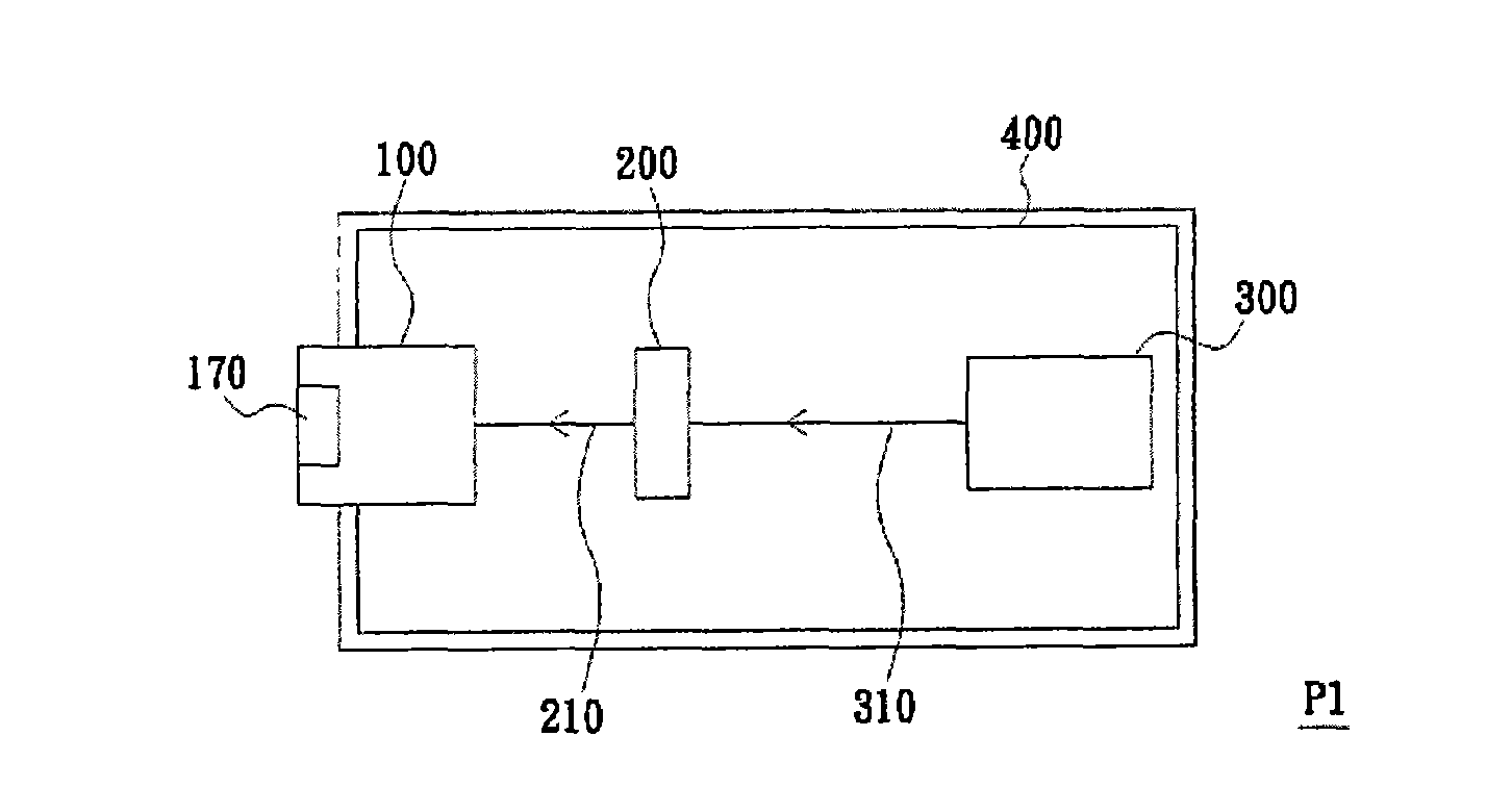
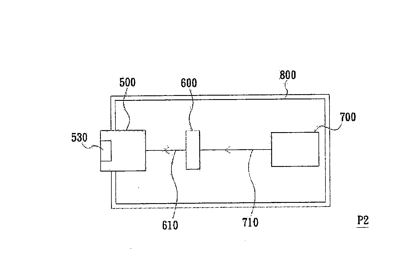
[0077] image 3 A schematic diagram of a projector according to the first embodiment of the present invention is shown. Please refer to image 3 , the projector P2 of this embodiment includes a lens adjustment module 500 , a light valve 600 , an illumination module 700 and a cover 800 . The lighting module 700 disposed in the cover body 800 provides an lighting beam 710 . The light valve 600 is disposed inside the cover body 800 and located on the transmission path of the illumination beam 710 . The light valve 600 converts the illumination beam 710 into an image beam 610 . The lens adjustment module 500 is disposed on the cover body 800 , and a lens 530 of the lens adjustment module 500 is located on the transmission path of the image beam 610 to project the image beam 610 to a screen (not shown).

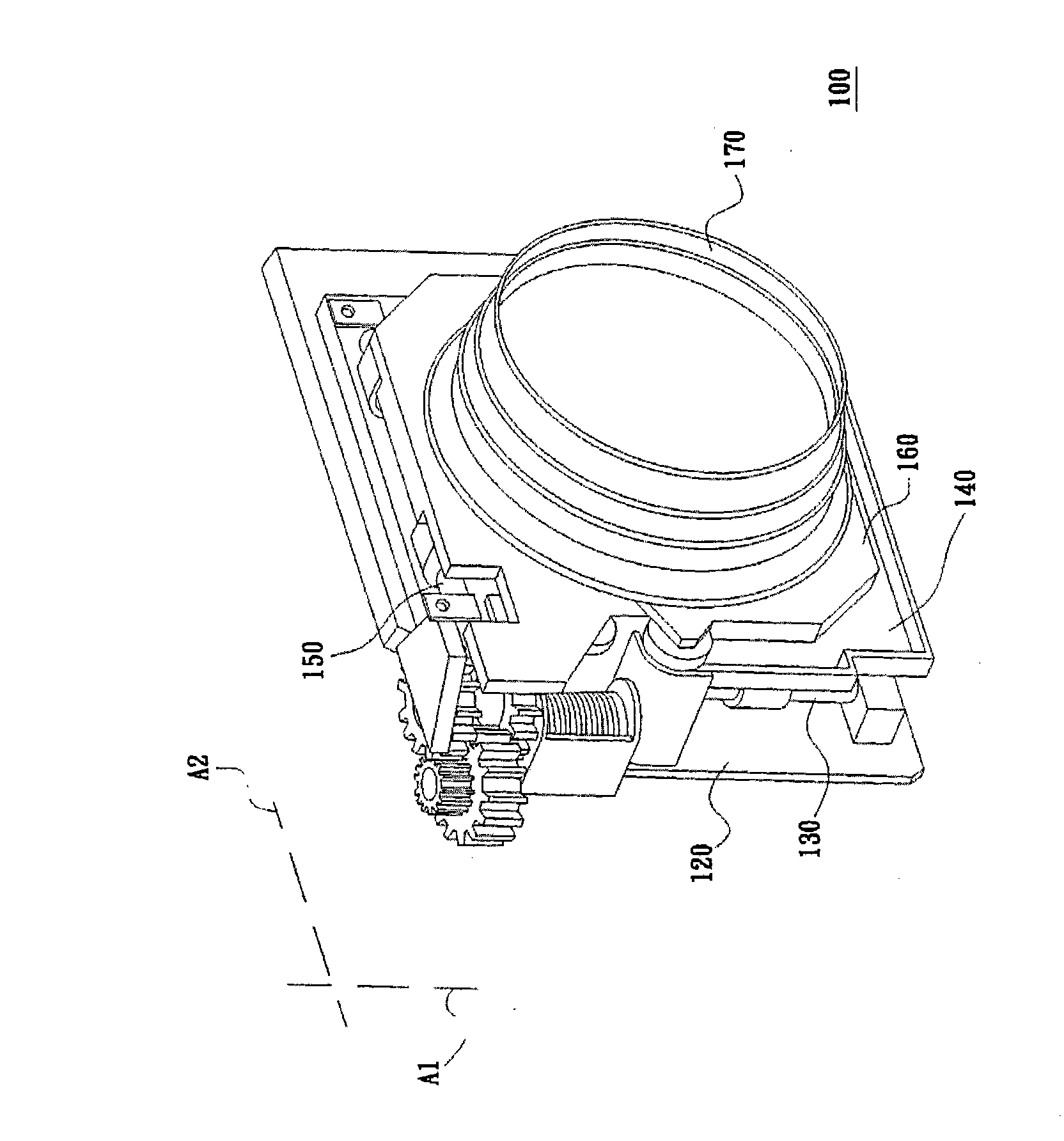
[0078] Figure 4A draw image 3 Combination diagram of the lens adjustment module, Figure 4B draw Figure 4A An exploded schematic of the lens adjustment module. Figure...

no. 2 example

[0092] Figure 9 An exploded view of a lens adjustment module according to a second embodiment of the present invention is shown. Figure 10A draw Figure 9 A detailed exploded schematic of the carrier plate. Figure 10B draw Figure 9 Another detailed exploded schematic diagram of the carrier plate. Figure 11 draw Figure 9 A detailed exploded schematic diagram of the adjustment device. Figure 12 draw Figure 9 A schematic diagram of the connection relationship between the adjustment device and the carrier plate. It is worth noting here that, for the sake of illustration, Figure 12 Only some of these components of the adjustment device 540' are shown schematically. Please refer to Figure 4B , Figure 5 , Figure 6A , Figure 9 , Figure 10A , Figure 10B and Figure 11 The main difference between the lens adjustment module 500' of this embodiment and the lens adjustment module 500 of the first embodiment lies in the appearance and configuration of the first...


PUM


Abstract

The invention discloses a lens regulation module which comprises a base, a bearing disc, a lens and a regulating device, wherein the bearing disc can be movably arranged on the base, the lens is fixedon the bearing disc, the regulating device comprises a shell, a worm, a transmission gear and a transmission part, the shell is fixed on the base, the worm is pivoted to the shell, the transmission gear is pivoted to the shell and meshed with the worm, and the transmission part is fixed at the transmission gear and connected to the bearing disc. When rotation of the worm drives the transmission gear to rotate, the transmission gear drives the transmission part to lead the bearing disc to move along the axial direction relative to the base. A configuration mode of the components of the lens regulation module can satisfy different needs of designers to space planning.

Description

technical field [0001] The present invention relates to a lens-adjusting module, and in particular to a lens-adjusting module applied to a projector. Background technique [0002] figure 1 A schematic diagram of an existing projector is shown. figure 2 draw figure 1 Schematic diagram of the lens adjustment module. Please refer to figure 1 and figure 2 , the existing projector P1 includes a lens adjustment module 100 , a light valve (light valve) 200 , an illumination module (illumination module) 300 and a cover body (cover) 400 . The illumination module 300 disposed in the cover 400 provides an illumination beam 310 . The light valve 200 is disposed inside the cover 400 and located on a transmission path of the illumination beam 310 . The light valve 200 converts the illumination beam 310 into an image beam (image beam) 210 . The lens adjustment module 100 is disposed on the cover body 400 , and a lens (lens) 170 of the lens adjustment module 100 is located on the ...

Claims


Application Information

Patent Timeline
IPC IPC(8): G02B7/04
Inventor 曾涌泉
Owner CORETRONIC
Why Eureka
Try Eureka