
Multi-dimensional optical control device and multi-dimensional optical control method

An optical control, multi-dimensional technology, applied in instruments, electrical digital data processing, input/output of user/computer interaction, etc., can solve the problems of increased part volume and cost, poor contact, unfavorable development, etc., to reduce energy consumption , The effect of reducing the problem of part positioning and optimizing the sensing sensitivity

Inactive Publication Date: 2010-03-17
IND TECH RES INST
View PDF8 Cites 3 Cited by
  • Summary
  • Abstract
  • Description
  • Claims
  • Application Information

AI Technical Summary

Problems solved by technology

[0005] US 6,333,733 installs light sources, screens, and optical sensors on three axes of space, and the three light sources operate simultaneously to complete the space control function, but US 6,333,733 requires multiple light sources, multiple screens, and optical sensors, so it can Consumption, number of parts, parts positioning, volume and other issues are unfavorable factors for its development
[0006] In US 2006 / 0086889A1, six light sources, six slit baffles and six optical sensors are installed in the space, and the six light sources are activated to complete the space control function, but US 2006 / 0086889A1 requires six light sources and slit baffles And optical sensors, so energy consumption, number of parts, part positioning, and volume issues are unfavorable factors for its development
[0007] US 6,480,183 uses the principle of capacitive sensing to sense the actuation of the conductor of the mover to complete the plane displacement and rotation control functions. However, due to the use of capacitive sensing, the relative position of the conductor and the sensing plate is limited, so direct space control cannot be performed. Function
[0008] US 5,969,520 uses multiple magnetic components to sense the movement of the magnetic ball to complete the plane control function; however, the relative position of the magnetic ball and the magnetic component will affect the sensing accuracy of the magnetic component. In addition, the magnetic component is susceptible to external magnetic conduction. The interference of objects will affect the position determination, and the magnetic ball will also attract and collide with external magnetic objects.
[0009] US 6,774,887 completes the plane control function through the contact between the conductor and the resistor, but the conductor and the resistor are easily affected by moisture or oxidation, resulting in poor contact, and if the space control function is to be achieved, other conductors and resistors must be installed, so that Part volume and cost increase

Method used


Image

  • Multi-dimensional optical control device and multi-dimensional optical control method
  • Multi-dimensional optical control device and multi-dimensional optical control method
  • Multi-dimensional optical control device and multi-dimensional optical control method

Examples


Embodiment Construction

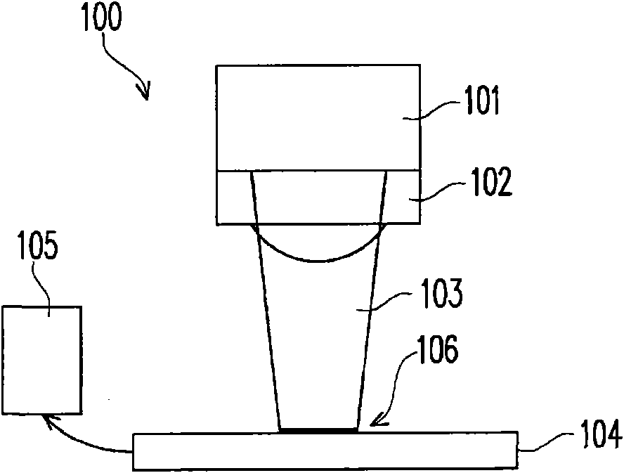
[0045] The basic concept of the present invention is to use the operation of the optical control device to change the position, shape or light intensity of the focused spot of the light beam generated by the internal light source on the sensor to generate a suitable control signal, and through this control signal, at the application end ( Such as: monitor) produces corresponding movements or actions. Next, multiple implementation examples will be used for illustration.

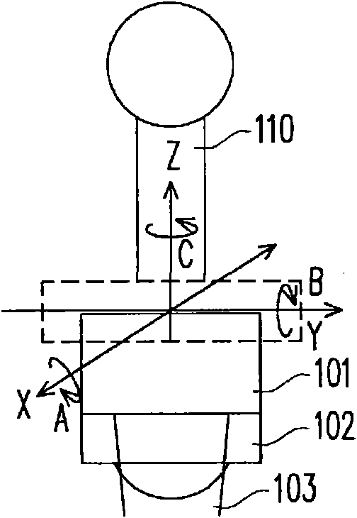
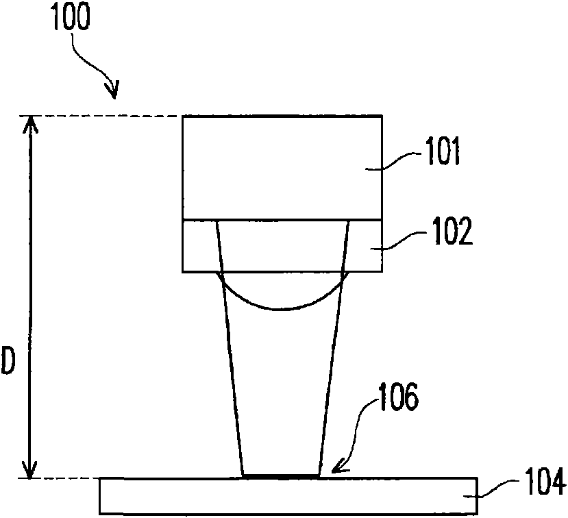
[0046] Figure 1A A schematic diagram showing the structure of the multi-dimensional optical control device of this embodiment example, Figure 1B A schematic diagram of the operational dimensions of the multi-dimensional optical control device is shown. Such as Figure 1A As shown, the multi-dimensional optical control device 100 includes a movable light source 101 , a lens 102 , a sensor 104 and a data processing circuit 105 . The movable light source 101 can be moved by external action and used to generat...


PUM


Abstract

The invention discloses a multi-dimensional optical control device and a multi-dimensional optical control method. The multi-dimensional optical control device comprises a movable light source, a lens, a sensor and a data processing circuit. The movable light source can move under external action and is used for generating light beams. The lens can be coupled with the movable light source to focus the light beams. The sensor is used for sensing a facula focused on the sensor. The data processing circuit is coupled to the sensor and is used for get the position variable quantity, the shape variable quantity and the light intensity variable quantity of the facula on the sensor, wherein the position variable quantity, the shape variable quantity and the light intensity variable quantity are relative to the position, the shape and the light intensity of a reference facula; in addition, the data processing circuit outputs a control signal according to the position variable quantity, the shape variable quantity and the light intensity variable quantity so as to carry out multi-dimensional control action, such as rotating and moving.

Description

technical field [0001] The present invention relates to an optical control device, and in particular to a multi-dimensional optical control device. Background technique [0002] Applied to the control methods of existing digital creation, industrial design or related electronic products, such as: keyboard, mouse, touch panel and other flat control devices, with the development of technology industry and the development of related products, when users need to use space six For three-dimensional control, the existing two-dimensional control device can no longer meet the needs of users. It must be equipped with other control devices, such as buttons, keyboards, etc., to complete the six-dimensional control function, which not only increases the difficulty of control , Using the wrist joint for a long time is easy to fatigue and even cause injury; in addition, the control method of replacing space with a plane is not an intuitive control method of the human body, which often lea...

Claims


Application Information

Patent Timeline
Patent Type & Authority Applications(China)
IPC IPC(8): G06F3/03G06F3/038
Inventor 蔡孟哲王雍行林柏衡陈佳旭詹启锋
Owner IND TECH RES INST
Learn More