
Method for drying grain and grain drier

A drying method and dryer technology, which are applied in dryers for static materials, drying solid materials, local stirring dryers, etc., can solve the problems of leaking hot air and cumbersome operations, and achieve the effect of improving efficiency.

Active Publication Date: 2010-03-24
SATAKE CORP +1
View PDF6 Cites 13 Cited by
  • Summary
  • Abstract
  • Description
  • Claims
  • Application Information

AI Technical Summary

Problems solved by technology

[0004] However, such net bags generally weigh 30 to 60 kg per bag, so it is a heavy labor to stack and arrange them in the flat dryer by manpower.
Moreover, a gap is generated between the side wall of the flat dryer and the mesh bag to leak hot air for drying, so the gap is blocked with unnecessary newspapers or suitable sponge materials to prevent the hot air from leaking, but There is a problem that the job is cumbersome

Method used


Image

  • Method for drying grain and grain drier
  • Method for drying grain and grain drier
  • Method for drying grain and grain drier

Examples


Embodiment 1

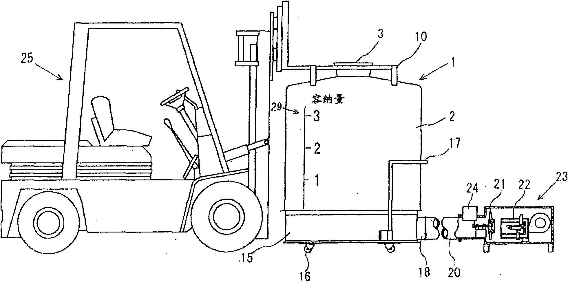
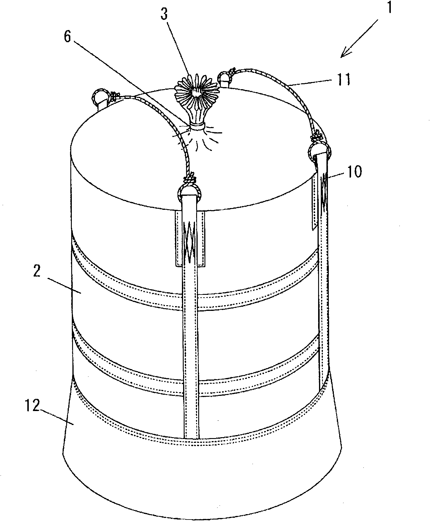
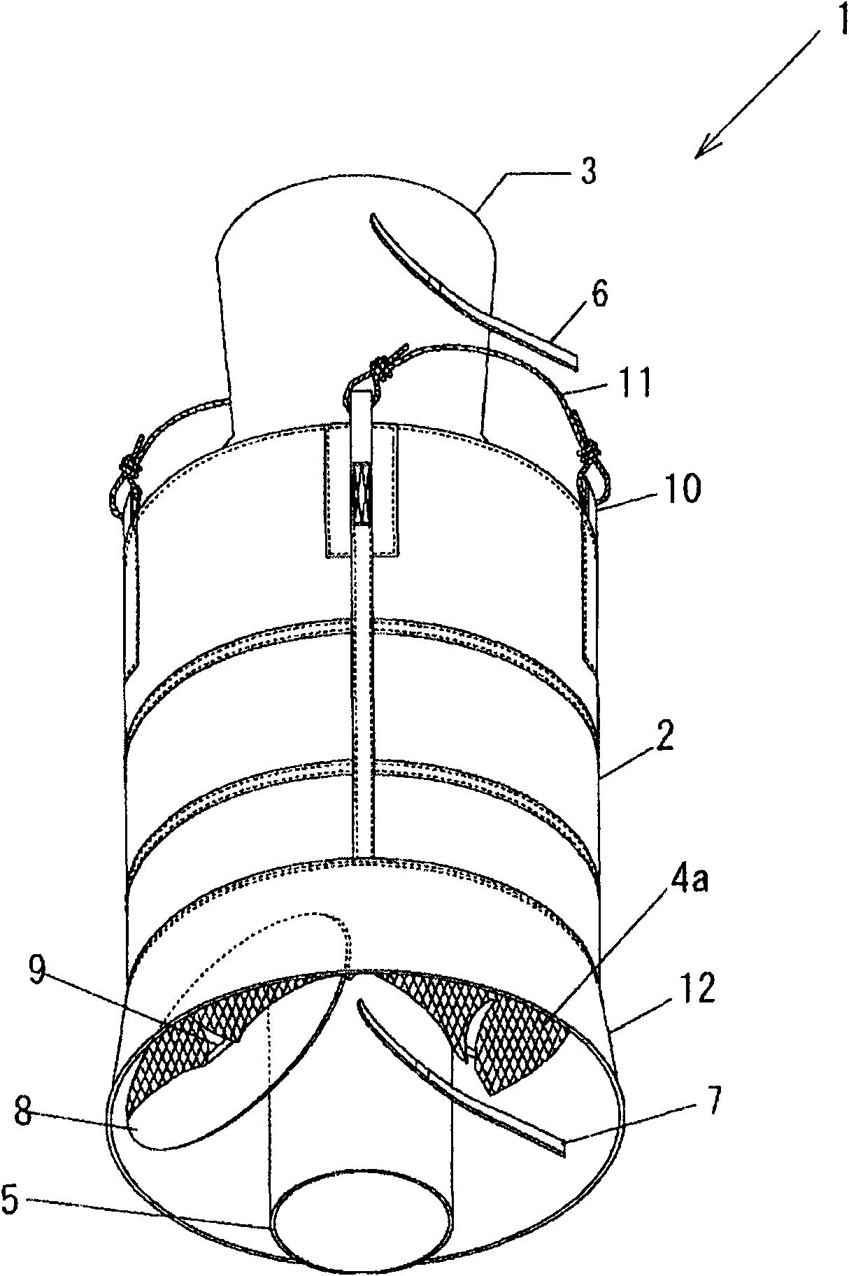
[0030] figure 1 It is a front view which shows the state which lifted the flexible container 1 which accommodated the paddy by the forklift 25 etc., and placed on the cylindrical drying casing 15 of the ventilation dryer. figure 2 It is a perspective view for showing the detailed structure of the flexible container 1 seen from the inlet side. image 3 It is a perspective view for showing the detailed structure of the flexible container 1 seen from the outlet side. Figure 4 It is a bottom view showing the bottom surface of the flexible container 1 .

[0031] Such as Figure 1 to Figure 4 As shown, the flexible container 1 is formed of polyvinyl chloride, polypropylene, etc., and mainly includes: a roughly cylindrical shell part 2 with a height of about 1.25m and a diameter of about 1.3m; The input port 3; the bottom surface 4 formed on the air-permeable net 4 ( Figure 4 ); and the central opening of the bottom surface 4, and the cylindrical discharge port portion 5 is co...

Embodiment 2

[0050] Figure 7 It is the second embodiment, which is a structure capable of fastening the skirt 12 of the flexible container 1 . Other structures are the same as in Embodiment 1.

[0051] Such as Figure 7 Shown in (a), a small channel-shaped rope-threading portion 13 ( Figure 9 ), and pass through the binding rope 14. By tightening the binding cord 14, the area of ​​the opening 28 of the skirt 12 can be reduced. And, if Figure 7 Shown in (b), tighten the binding cord 14 and reduce the area of ​​the opening 28 of the skirt portion 12, and place it on the drying housing 15 in this state ( Figure 8 ).

[0052] Figure 9 yes Figure 8 The enlarged sectional view of the main part of the part surrounded by the symbol A is placed on the drying shell 15 after reducing the area of ​​the opening 28 of the skirt 12, and then the skirt 12 bulges slightly toward the outer direction of the side wall 15a of the drying shell 15. , and the lower periphery of the skirt 12 is sand...


PUM

PropertyMeasurementUnit
Diameteraaaaaaaaaa
Radiusaaaaaaaaaa

Abstract

The present invention provides a method for drying grain and a grain drier, capable of drying about 1000kg of grain simultaneously without heavy work and fussy operations of processing grain and supplying wind for drying without lose. The grain drier is composed of a flexible container (1) and an air dryer. The flexible container (1) is provided with an input port (3) on the top, the bottom face of the flexible container (1) is formed by an air permeability net (4a), and the lower part circumference face of the flexible container is provided with a skirt part (12). The air drier is provided with a drying casing (15) contacted with and enclosing the bottom face or bottom of the flexible container (1), and a floor through which hot wind may pass to dry the contained grain. The flexible container (1) is arranged on the air drier, such that the lower circumference of the skirt part (12) is clinged to the external face of the drying casing (15).

Description

technical field [0001] The present invention relates to a grain drying method and a grain drying machine. Background technique [0002] Regarding rice harvesting, conventionally, rice harvested by a combine harvester that reaps and threshes while moving automatically is stored in a plurality of mesh bags at the same time as harvesting. Using a flat-type dryer for rice drying (a dryer with a floor that can be blown by installing horizontal bars at intervals, and sending air for drying from below the floor), the rice packed in mesh bags is dried, for example, The paddy rice with a moisture content of 25% at the time of harvest is dried by ventilating for about 10 hours until the moisture content reaches about 17%. This grain drying method is recorded in the Japanese Patent Publication No. 58-57670. [0003] Above-mentioned drying method is on the floor that can carry out air supply in the planar drier, the net bag that paddy is housed is arranged and paved, and the arrangeme...

Claims


Application Information

Patent Timeline
IPC IPC(8): F26B9/06F26B3/02F26B25/06F26B25/08
CPCA23B9/02A23B9/08F26B17/14F26B21/02
Inventor 中冈清典中上信一
Owner SATAKE CORP
Learn More