
Image processing apparatus, image processing method, imaging apparatus

一种图像处理设备、运动矢量的技术,应用在图像数据处理、图像增强、图像分析等方向,能够解决模糊图像的组判断错误等问题

Inactive Publication Date: 2010-03-31
CANON KK
View PDF2 Cites 10 Cited by
  • Summary
  • Abstract
  • Description
  • Claims
  • Application Information

AI Technical Summary

Problems solved by technology

[0021] Therefore, if the background and the moving subject are similar in degree of dispersion, or if the moving subject gradually becomes larger, there will be misjudgment of the area that needs correction of blurred images due to camera shake, or the group that needs correction of blurred images

Method used


Image

  • Image processing apparatus, image processing method, imaging apparatus
  • Image processing apparatus, image processing method, imaging apparatus
  • Image processing apparatus, image processing method, imaging apparatus

Examples


Embodiment Construction

[0067] Various exemplary embodiments, features, and aspects of the present invention will be described in detail below with reference to the accompanying drawings.

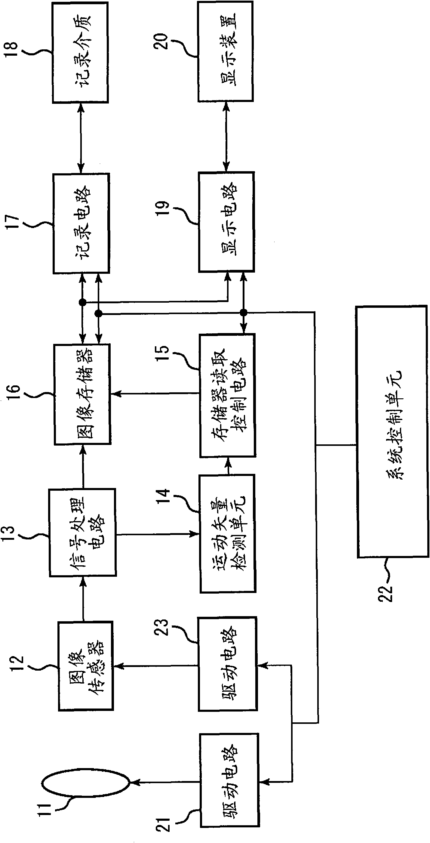
[0068] figure 1 is a block diagram showing the structure of a video camera or a camera as an image pickup apparatus including the image processing apparatus according to an exemplary embodiment of the present invention. The present invention is applicable to any video camera employing interlace scan or progressive scan. In the following exemplary embodiments, image data obtained by a video camera during a vertical synchronization period is described as field image data. However, it is not limited to this. In other words, in the following exemplary embodiments, the term "frame" may be substituted for the term "field".

[0069] exist figure 1 Among them, the imaging optical system 11 includes a lens and a diaphragm. The image sensor 12 includes a Charge Coupled Device (CCD) or Complementary Metal Oxide Semico...


PUM


Abstract

An image processing apparatus includes a motion vector detecting unit configured to detect, for each field of a signal, a motion vector in each of a plurality of vector detection areas within the field, a determining unit configured to determine, for each field, a group area obtained by grouping the motion vector detection areas based on the motion vector detected by the motion vector detecting unit, a geometric center calculation unit configured to obtain, for each field, a geometric center of the group area, a determination unit configured to determine group areas that correspond to each other in fields that are in consecutive relation in terms of time by comparing the geometric centers of the group areas obtained for each field in consecutive relation.

Description

technical field [0001] The present invention relates to an image processing apparatus and image processing method for correcting camera shake to prevent blurring of a moving image captured by a video camera or the like. Background technique [0002] For users of imaging apparatuses such as video cameras for capturing moving images, blurred images due to camera vibrations are a problem especially when zooming a focus lens at the telephoto end. [0003] In order to prevent such image blur due to camera vibration, a technique has conventionally been proposed that detects a motion vector of an image from a captured image signal, and corrects the image blur based on the detected motion vector. Japanese Patent Application Laid-Open No. 06-133298 describes an imaging device using this technique. [0004] Furthermore, a correlation method based on a correlation operation and a block matching method have conventionally been used as a method for detecting a motion vector of an image....

Claims


Application Information

Patent Timeline
Patent Type & Authority Applications(China)
IPC IPC(8): H04N5/232H04N5/14G06T7/20
CPCG06T2207/10016G06T2207/20021G06T7/2006H04N5/145H04N5/23248G06T7/215H04N23/68
Inventor 宫迫贤一
Owner CANON KK
Features
  • Generate Ideas
  • Intellectual Property
  • Life Sciences
  • Materials
  • Tech Scout
  • Unparalleled Data Quality
  • Higher Quality Content
  • 60% Fewer Hallucinations
Learn More