Method and device for realizing load transfer

A technology of load transfer and load information, which is applied in the field of communication, can solve the problem of not being able to effectively reduce the load of network nodes, and achieve the effect of easy maintenance, operation and management, and avoiding overload

Active Publication Date: 2010-03-31
SHANGHAI HUAWEI TECH CO LTD
View PDF0 Cites 20 Cited by
  • Summary
  • Abstract
  • Description
  • Claims
  • Application Information

AI Technical Summary

Problems solved by technology

[0010] In summary, the inventors found that the load transfer scheme in the prior art cannot effectively reduce the load of network nodes

Method used


Image

  • Method and device for realizing load transfer
  • Method and device for realizing load transfer
  • Method and device for realizing load transfer

Examples


Embodiment 1

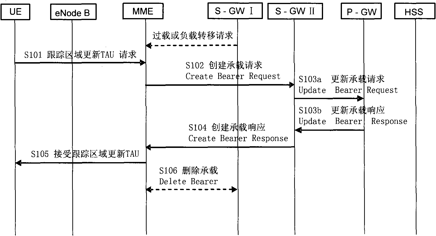
[0034] The load transfer solution of the serving gateway S-GW provided in this embodiment is to perform load transfer when the user terminal UE performs a Tracking Area Update (TAU, Tracking Area Update). figure 1 , the process includes the following steps:

[0035] 101. The UE sends a tracking area update TAU request message to a mobility management entity MME.

[0036] Since the mobility management entity MME has already known the load status information of the serving gateway S-GW before receiving the TAU request message, specifically, the following methods can be used:

[0037] After the S-GW is overloaded, the MME is notified through an explicit message; or, the MME determines that the S-GW has been overloaded through the "load balancing mechanism selected by the S-GW".

[0038] In addition, even if the S-GW is not overloaded, it may be decided to transfer the load of the S-GW for operation and maintenance management. At this time, the S-GW notifies the MME through an ex...

Embodiment 2

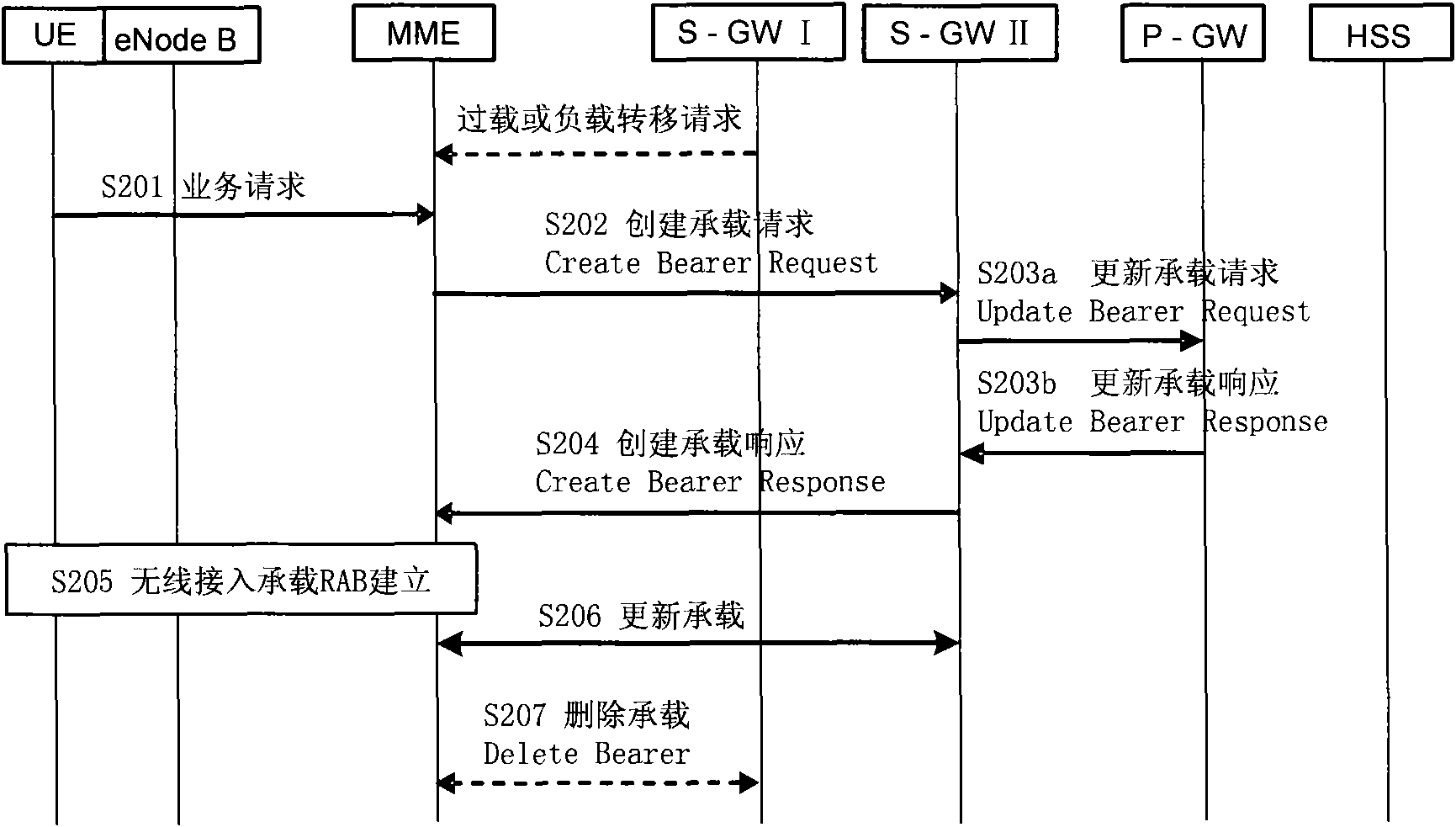
[0046] The load transfer scheme of the service gateway S-GW provided in this embodiment is to perform load transfer when the user terminal UE performs a service request (Service Request). Refer to figure 2 , the process includes the following steps:

[0047] 201. The UE sends a Service Request message to the MME;

[0048] The mobility management entity MME has already known the load status information of the serving gateway S-GW before receiving the service request message, specifically through the following methods:

[0049] After the S-GW is overloaded, the MME is notified through an explicit message; or, the MME determines that the S-GW has been overloaded through the "load balancing mechanism selected by the S-GW".

[0050] In addition, even if the S-GW is not overloaded, it may be decided to transfer the load of the S-GW for operation and maintenance management. At this time, the S-GW notifies the MME through an explicit message, for example, a load transfer request messa...

Embodiment 3

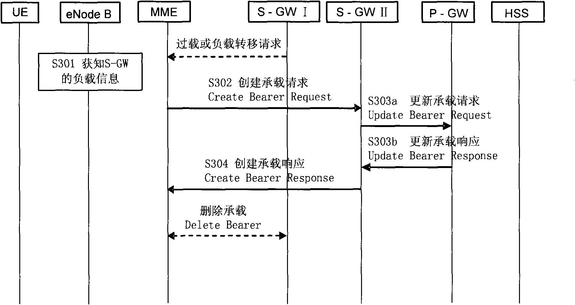
[0058] The load transfer scheme of the serving gateway S-GW provided in this embodiment is to transfer the load of the user terminal UE in the idle state, refer to image 3 , the process includes the following steps:

[0059] 301. The MME obtains the load condition of the S-GW in advance;

[0060] After the S-GW is overloaded, the MME is notified by an explicit message; or, the MME determines that the S-GW is overloaded through the "load balancing mechanism selected by the S-GW"; when the S-GW is not overloaded, the S-GW can also It is necessary to decide to transfer the load. At this time, the S-GW notifies the MME through an explicit message, for example, a load transfer request message.

[0061] 302. The MME determines that the S-GW has been overloaded or that the S-GW requires to transfer the load of one or some UEs, then the MME selects a new non-overloaded S-GW for the UE to transfer the load of the original S-GW. The load is transferred. At this time, the UE is in the...


PUM


Abstract

The embodiment of the invention discloses a method for realizing load transfer, which comprises the following steps: receiving the overload information or a load transfer request of a first service gateway; transferring user equipment (UE) to a second service gateway which is not overloaded, and establishing bearing between the UE and the second service gateway; and updating the corresponding bearing information between the second service gateway and a corresponding packet data network gateway. According to the embodiment of the invention, a novel service gateway is selected to the UE to be transferred when a condition that the load of the service gateway needs to be transferred is judged, and the corresponding bearing of the novel service gateway is established so as to complete transferring. Thus, by the load redistribution of user face nodes, the load transfer on the service gateway is realized, the overload of the service gateway is avoided, and the maintenance operation and the management are convenient.

Description

technical field [0001] The present invention relates to the technical field of communications, in particular to a method and device for realizing load transfer. Background technique [0002] Currently in 3GPP, various vendors are actively researching on Long Term Evolved (LTE, Long Term Evolved) / System Architecture Evolved (SAE, System Architecture Evolved). The low-cost network with system capacity and coverage uses PS domain services, and the bearer network is IP bearer. The determined LTE / SAE network architecture is shown in the figure. [0003] In the evolved packet core network, the function of the Mobility Management Entity (MME, Mobility Management Entity) is to save the UE's mobility management context, such as user identity, mobility management status, location information, etc., and provide information to the non-access stratum ( NAS, NonAccess Stratum) signaling processing, responsible for the security of NAS signaling, etc. [0004] The SAE gateway (SAE GW) in...

Claims


Application Information

Patent Timeline
Patent Type & Authority Applications(China)
IPC IPC(8): H04W28/08H04L12/56
Inventor 张万强郭小龙
Owner SHANGHAI HUAWEI TECH CO LTD
Why Eureka
Try Eureka