Coke oven offtake piping system

A technology for discharging pipelines and coke ovens, which can be used in coke ovens, coke oven heating, dry distillation gas discharge devices, etc., and can solve problems such as no great progress in flow rate control.

Active Publication Date: 2010-03-31
PAUL WURTH SA
View PDF2 Cites 2 Cited by
  • Summary
  • Abstract
  • Description
  • Claims
  • Application Information

AI Technical Summary

Problems solved by technology

Although the valve is a reliable design, it does not provide a great improvement in flow rate control

Method used


Image

  • Coke oven offtake piping system
  • Coke oven offtake piping system
  • Coke oven offtake piping system

Examples


Embodiment Construction

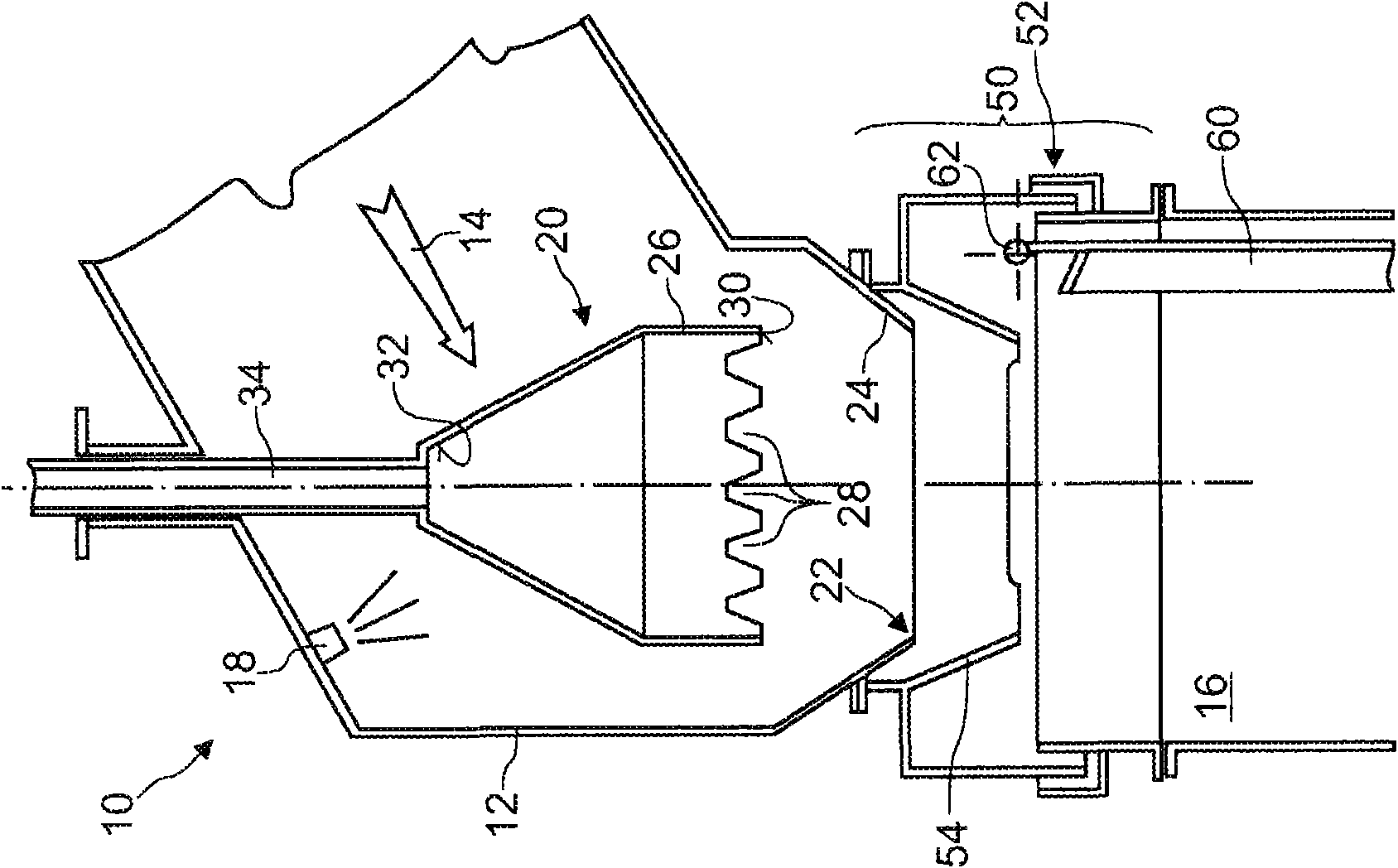
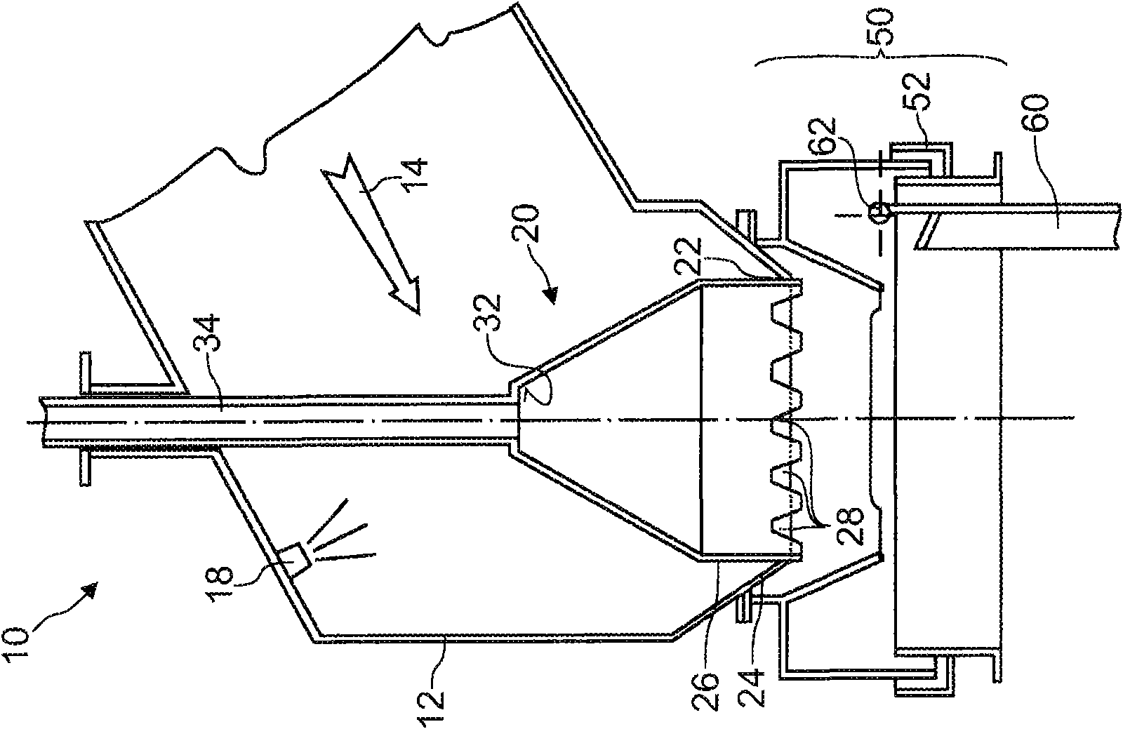
[0036] figure 1A first embodiment of a coke oven discharge piping system 10 according to the invention is shown. It includes piping assemblies for conveying untreated distillate gas from individual coke oven chambers to accumulation tubes. In this embodiment, the duct assembly includes a standpipe (not shown) whose bottom is connected to the top of a coke oven (not shown), such as a slot-type chamber of a coke oven battery. Reference numeral 12 designates a gooseneck (bent pipe) for conveying untreated coke oven gas (arrow 14) from the upper part of the standpipe to the accumulation pipe 16 of the coking plant, which typically runs the entire length of the coke oven battery . Conventionally, these piping pieces may have refractory linings. The gas discharged from the furnace chamber at a temperature of about 700°C to 800°C is advantageously cooled in the gooseneck 12 to a temperature of 80-100°C by means of one (or more) nozzles 18 (spraying a process fluid such as ammonia)...


PUM


Abstract

A coke oven piping system (10) comprises a pipe assembly for conveying coke oven gases (14) from a coke oven to a collecting main (16); and flow control means comprising a flow orifice (22) in the pipe assembly with an associated obturating member (20), the obturating member being axially moveable between an open position at a certain distance from the flow orifice to a closed position in which it substantially obstructs the flow orifice (22). At least one throttling opening (28) is arranged so as to offer, towards the end of the closing stroke of the obturating member (20), an opening area for the gases to the collecting main (16) that depends on the axial position of the obturating member (20).

Description

technical field [0001] The present invention relates generally to coke oven construction and more particularly to coke oven discharge piping with integrated flow control valves for regulating the flow of untreated gas from each individual coking chamber to the accumulation tube. Background technique [0002] Traditionally, in a coking plant comprising a bank of coke ovens, the untreated gases (distillate gas and steam) from each individual oven are directed through discharge pipes to accumulation pipes, which typically run throughout the battery of coke ovens. the entire length. The discharge piping itself usually consists of a standpipe (also known as a standpipe or riser) extending upwards from the furnace roof, and a gooseneck, ie a short bend that communicates with the top of the standpipe and leads to the accumulation pipe. One or more nozzles are provided in the gooseneck to cool the raw gas from about 700-800°C to a temperature of about 80-100°C. [0003] In order t...

Claims


Application Information

Patent Timeline
Patent Type & Authority Applications(China)
IPC IPC(8): C10B27/06F16K1/36
CPCC10B27/06F16K1/54Y10T137/0318
Inventor 埃米尔·洛纳尔迪托马斯·汉斯曼斯特凡诺·皮沃毛里齐奥·比索尼奥
Owner PAUL WURTH SA
Why Eureka
Try Eureka