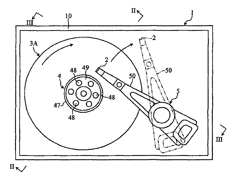
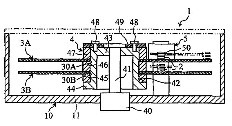
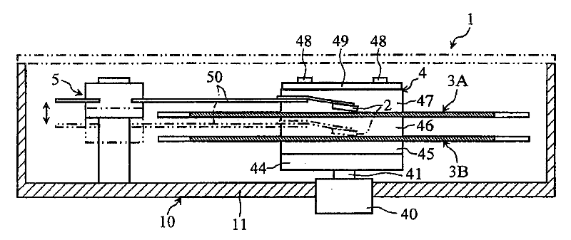
Substrate for magnetic head, magnetic head, and recording medium drive device
A magnetic head and substrate technology, applied in magnetic recording, magnetic recording head, configuration/installation of recording head, etc., can solve problems such as increased chip size, inhibition of grain growth, and low ratio of titanium carbide grains
- Summary
- Abstract
- Description
- Claims
- Application Information
AI Technical Summary
Problems solved by technology
Method used
Image
Examples
Embodiment 1
[0089] In this example, fourteen types of substrates for magnetic heads (sample Nos. 2 o 3 And the mass ratio of TiC, conductivity, density, number ratio of TiC crystal grains and machinability.
[0090] The substrate for a magnetic head is manufactured by pressure sintering after preparing a predetermined slurry to form a molded body.
[0091] The slurry is passed through the Al 2 o 3 powder, TiC powder, TiO 2 Powder, Yb 2 o 3 The powder, the binder for molding, and the dispersant were put into a glass bead mill in predetermined amounts, and glass beads for pulverization were produced using the average particle diameters shown in Table 1. The average particle diameter of the pulverized particle diameters of the raw materials in the slurry was measured by the light transmission centrifugal sedimentation method specified in JIS Z 8823-2:2004. Table 1 shows the measurement results of the pulverized particle diameters of the raw materials.
[0092] The molded article is f...
Embodiment 2
[0111] In this example, regarding the substrate for a magnetic head, the relationship between the average crystal grain size of TiC crystal grains and machinability was confirmed.
[0112] Basically, a substrate for a magnetic head was produced under the same conditions as in Example 1. However, in this example, five kinds of slurries were produced using the raw material of sample No. 8 (see Table 1) used in Example 1, and as shown in Table 2, the pulverization times of these five kinds of slurries were different. From these slurries, substrates for magnetic heads (No. 15 to 19) were produced.
[0113] The TiC content of the magnetic head substrate was determined by analyzing an image in the range of 5 μm × 8 μm taken with a scanning electron microscope (SEM) at a magnification of 13,000 times with image processing software (Image-Pro Plus, manufactured by Nihon Visual Science Co., Ltd.). The average crystal grain size of the grains. Table 2 shows the measurement results of ...
Embodiment 3
[0119] In this example, the relationship between the flexural strength and the machinability was confirmed for the substrate for a magnetic head.
[0120] Basically, a substrate for a magnetic head was produced under the same conditions as in Example 1. However, in this example, using the raw material of sample No. 8 (see Table 1) used in Example 1, after pressurizing and sintering the molded body, hot isostatic pressing sintering was carried out at the temperature shown in Table 3 ( HIP) for 1 hour to produce magnetic head substrates (No. 20 to 22).
[0121] The flexural strength of the substrate for a magnetic head was measured as a three-point flexural strength in accordance with JIS R 1601-1995. The measurement results of the three-point bending strength are shown in Table 3.
[0122] The machinability of the substrate for a magnetic head was basically evaluated as the maximum value of chips in the same manner as in Example 1. However, a diamond blade having the same sp...
PUM
| Property | Measurement | Unit |
|---|---|---|
| diameter | aaaaa | aaaaa |
| crystal size | aaaaa | aaaaa |
| flexural strength | aaaaa | aaaaa |
Abstract
Description
Claims
Application Information
 - R&D
- Intellectual Property
- Life Sciences
- Materials
- Tech Scout
- Unparalleled Data Quality
- Higher Quality Content
- 60% Fewer Hallucinations
Browse by: Latest US Patents, China's latest patents, Technical Efficacy Thesaurus, Application Domain, Technology Topic, Popular Technical Reports.
© 2025 PatSnap. All rights reserved.Legal|Privacy policy|Modern Slavery Act Transparency Statement|Sitemap|About US| Contact US: help@patsnap.com


