
Coaxial connector

A coaxial connector, axial technology, applied in the direction of connection, two-pole connection, two-part connection device, etc., to achieve the effect of a wide frequency range

Active Publication Date: 2012-07-04
ROSENBERGER HOCHFREQUENZTECHNIK GMBH & CO KG
View PDF1 Cites 0 Cited by
  • Summary
  • Abstract
  • Description
  • Claims
  • Application Information

AI Technical Summary

Problems solved by technology

However, when the coaxial interface is connected by plugging in, there is no change in electrical and mechanical characteristics

Method used


Image

  • Coaxial connector
  • Coaxial connector
  • Coaxial connector

Examples


Embodiment Construction

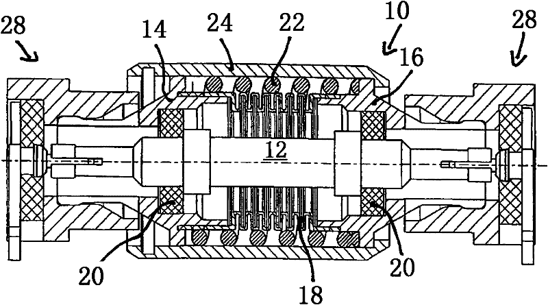
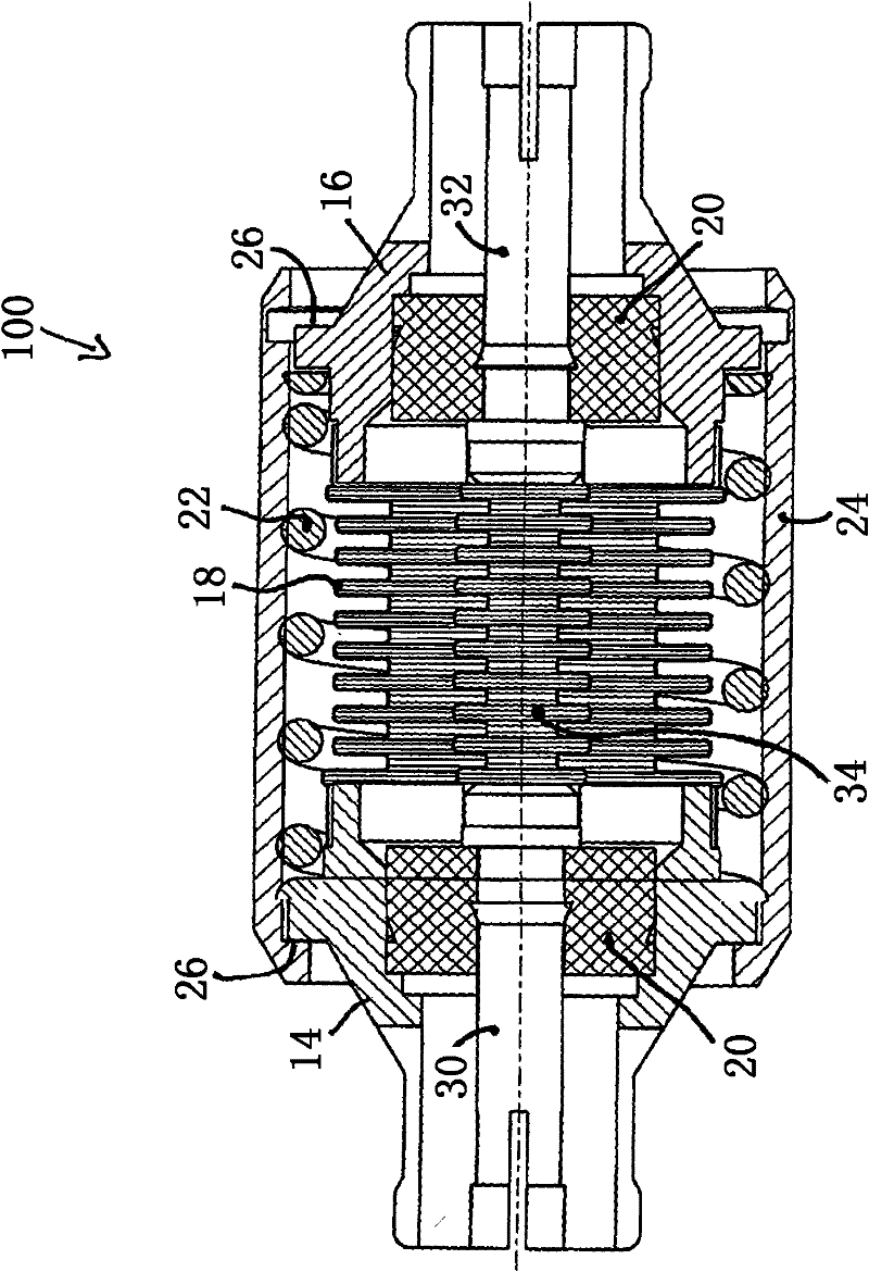
[0021] figure 1 with figure 2 The illustrated first preferred embodiment of the coaxial connector 10 according to the present invention includes a central conductor 12 and an outer conductor, the outer conductor being composed of a first outer conductor portion 14 and a second outer conductor portion 16, the first outer conductor portion 14 forms the first end of the outer conductor for insertion, and the second outer conductor portion 16 forms the second end of the outer conductor for insertion. Between the two outer conductor parts 14 and 16, the outer conductor is in the form of a telescopic outer conductor bellows 18. In this way, the two outer conductor portions 14, 16 can move relative to each other in the axial direction. The central conductor 12 is in a rigid form, and the central conductor 12 is held in the two outer conductor parts 14 and 16 by the insulating disk 20 so that the two outer conductor parts 14 and 16 can move relative to the central conductor 12 in the ...


PUM


Abstract

The invention relates to a coaxial connector (10, 100) comprising an outer conductor having a first plug-side end and a second plug-side end, axially opposite the first plug-side end of the outer conductor, and an inner conductor (12) having a first plug-side end and a second plug-side end, axially opposite the first plug-side end of the inner conductor. The invention is characterized in that theouter conductor has two separate outer conductor parts (14, 16), a first outer conductor part (14) forming the first plug-side end of the outer conductor and a second outer conductor part (16) forming the second plug-side end of the outer conductor. The two outer conductor parts (14, 16) of the outer conductor are arranged and configured in such a manner that they are mobile relative to each other in the axial direction, the outer conductor being configured as an outer conductor bellows (18) between the two outer conductor parts (14, 16). A first elastic spring element (22) is provided on theouter conductor and acts upon the two outer conductor parts (14, 16) of the outer conductor in the axial direction, driving them away from each other. The outer conductor bellows (18) is configured in such a manner that upon a change in length of the outer conductor bellows (18) a changing capacitance of the outer conductor bellows (18) is compensated by a correspondingly changing opposite inductance of the outer conductor bellows (18) in such a manner that the characteristic impedance of the coaxial connector (10, 100) remains substantially constant upon a change in length of the outer conductor bellows (18).

Description

Technical field [0001] The present invention relates to a coaxial connector having an outer conductor and a central conductor. As defined in the preamble of claim 1, the outer conductor has a first end for insertion and a second end for insertion. The insertion of the outer conductor The second end is located at a position opposite to the first end for insertion of the outer conductor, the center conductor has a first end for insertion and a second end for insertion, and the second end for insertion of the center conductor is located for insertion with the center conductor. The first end is at the opposite axial position. Background technique [0002] A coaxial connection part is known from DE 102004044975 A1, which has an outer conductor sleeve and a central conductor for connecting a coaxial socket to a circuit carrier. An elastic bending bellows made of conductive material is arranged in the central conductor to keep the axial force and the radial force appearing in the entra...

Claims


Application Information

Patent Timeline
Patent Type & Authority Patents(China)
IPC IPC(8): H01R24/54H01R13/646
CPCH01R13/6315H01R24/542H01R24/44H01R2103/00
Inventor B·罗森伯格
Owner ROSENBERGER HOCHFREQUENZTECHNIK GMBH & CO KG
Learn More