
Rear registration plate lamp assembly of motorcycle

A technology for license plate lights and motorcycles, which is applied to motor vehicles, road vehicles, lighting devices, etc., can solve problems such as difficulty in drawing molds smoothly, increasing the difficulty of mold manufacturing and injection molding processes, and reducing the appearance and commerciality of rear license plate lights. Achieve the effect of improving the appearance of merchandise, easy demoulding, reliable connection and sealing

Active Publication Date: 2010-04-21
CHONGQING LONCIN MOTOR
View PDF1 Cites 0 Cited by
  • Summary
  • Abstract
  • Description
  • Claims
  • Application Information

AI Technical Summary

Problems solved by technology

In the existing rear license plate lamp, the lamp holder and the lamp housing are connected by fastening relative to the front and back, because the white light of the license plate lamp is reflected by the reflective surface parallel to the beam direction, in order to meet the requirements of the national standard that the white light is not exposed, and because the lamp holder Due to the limitation of the structure used to install the light bulb, the inclination of the transparent white sheet on the lamp housing of the rear license plate lamp of the existing two-wheeled motorcycle relative to the horizontal plane does not exceed 2° at most, which limits the use of the rear license plate lamp to a large extent. Therefore, the outer contour of the lamp housing of the traditional rear license plate lamp is usually made into a regular cube shape, which not only reduces the appearance and commerciality of the rear license plate lamp, but also is not easy to achieve smooth drafting during manufacturing, and increases the mold manufacturing and injection molding. Difficulty of craft

Method used


Image

  • Rear registration plate lamp assembly of motorcycle
  • Rear registration plate lamp assembly of motorcycle
  • Rear registration plate lamp assembly of motorcycle

Examples


Embodiment Construction

[0012] The present invention will be further described below in conjunction with drawings and embodiments.

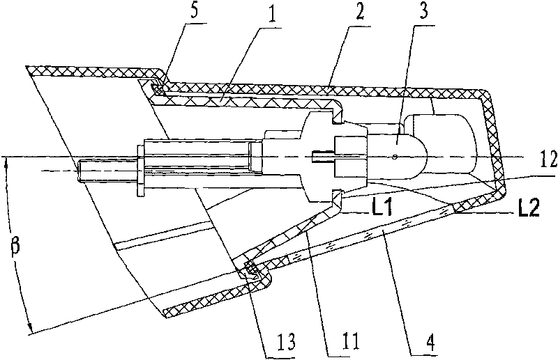
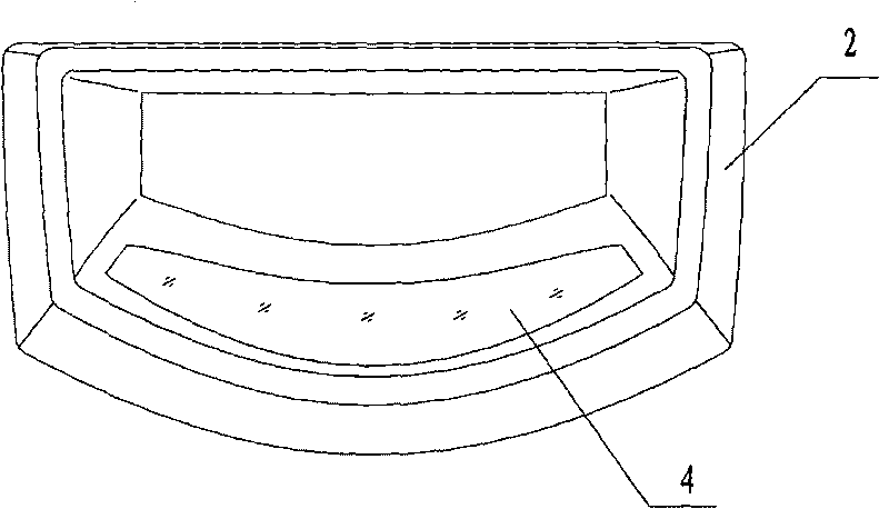
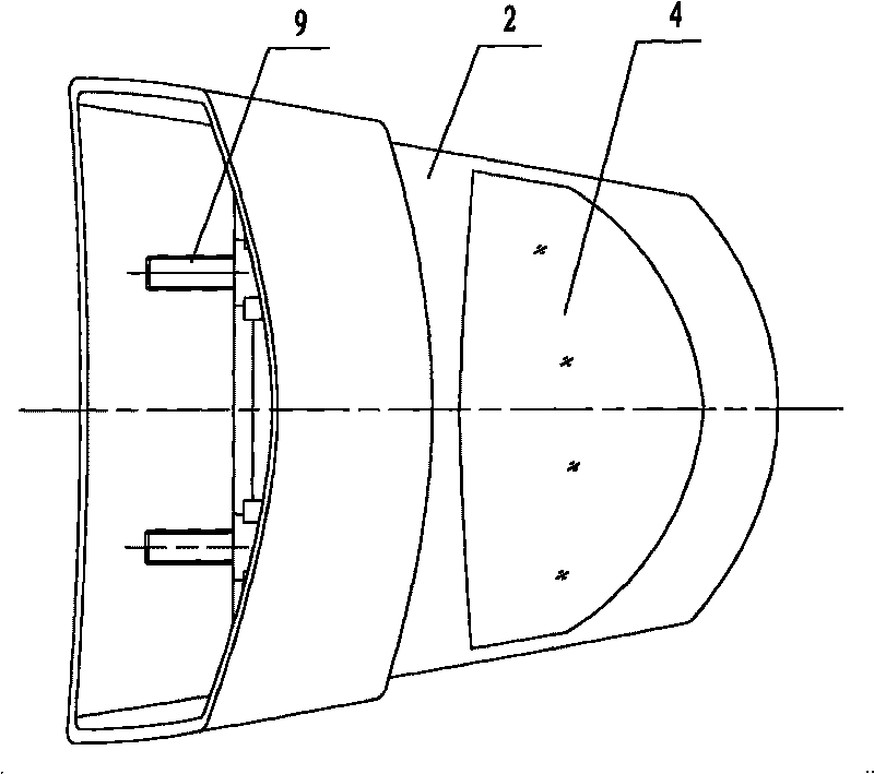
[0013] Such as figure 1 , figure 2 and image 3 As shown, a motorcycle rear license plate light assembly of the present invention has a lamp holder 1, a lamp housing 2 and a bulb 3, the bulb 3 is installed on the lamp holder 1, the lamp housing 2 is connected with the lamp holder 1, and the lamp housing 2 A transparent white sheet 4 is arranged on the lower side relative to the position of the light bulb 3 . Moreover, the lamp holder 1 is installed in the lamp housing 2, the backlight surface 11 on the lamp holder 1 below the light bulb 3 and the surface of the transparent white sheet on the lamp housing 2 are all slopes relative to the horizontal plane, and the lamp holder 1 is facing the light bulb 3 The reflective surface 12 is perpendicular to the horizontal plane, and the lower edge L1 of the reflective surface 12 is higher than the upper edge L2 of the outer s...


PUM


Abstract

The invention relates to a rear registration plate lamp assembly of a motorcycle, which is provided with a lamp holder (1), a lamp shell (2) and a bulb (3), wherein the bulb (3) is arranged on the lamp holder (1); the lamp shell (2) is connected with the lamp holder (1); and a position on the lower lateral surface of the lamp shell (2) relative to the bulb (3) is provided with a transparent white film (4). Besides, the lamp holder (1) is arranged in the lamp shell (2), a backlight surface on the lamp holder (1) and positioned below the bulb (3), and the surface of the transparent white film on the lamp shell (2) are inclined planes relative to a horizontal plane, a light reflecting surface on the lamp holder (1) and opposite to the bulb (3) is vertical to the horizontal plane, and the lower edge of the light reflecting surface is higher than the upper edge of an outer lateral surface of the transparent white film (4). The rear registration plate lamp assembly of the motorcycle makes a rear registration plate lamp of the motorcycle more convenient for manufacturing on the premise of no exposed light according to national standards, and is helpful for improving the appearance commodity of the rear license plate lamp.

Description

technical field [0001] The invention relates to motorcycle parts, especially motorcycle rear license plate lights. Background technique [0002] According to the provisions of the national standard GB18100-2000, the observer cannot see the white light within a certain distance behind the two-wheeled motorcycle and within a certain angle range relative to the symmetrical center of the vehicle, that is, the white light of the rear license plate light is not exposed. In the existing rear license plate lamp, the lamp holder and the lamp housing are connected by fastening relative to the front and back, because the white light of the license plate lamp is reflected by the reflective surface parallel to the beam direction, in order to meet the requirements of the national standard that the white light is not exposed, and because the lamp holder Due to the limitation of the structure used to install the light bulb, the inclination of the transparent white sheet on the lamp housing ...

Claims


Application Information

Patent Timeline
IPC IPC(8): F21S8/10F21V19/00F21V7/04F21V15/02B62J6/00F21W101/027F21W107/17
Inventor 毛开健
Owner CHONGQING LONCIN MOTOR
Learn More