Quick-change type guide sleeve fixing structure

A fixed structure and guide sleeve technology, applied in the direction of forming tools, metal processing equipment, manufacturing tools, etc., can solve the problems of long replacement time, affecting the normal production of enterprises, and low mold precision, so as to achieve convenient operation, high quality and production efficiency. , the effect of structural stability

Inactive Publication Date: 2010-05-12
皇裕精密技术(苏州)有限公司
View PDF0 Cites 1 Cited by
  • Summary
  • Abstract
  • Description
  • Claims
  • Application Information

AI Technical Summary

Problems solved by technology

[0003] The invention provides a quick-change guide sleeve fixing structure, which solves the problem in the prior art that the replacement time of the glue-filled guide sleeve is long after wear and affects the normal production of the enterprise, and also solves the problem of the glue-filled guide sleeve fixing structure The problem of low mold precision

Method used


Image

  • Quick-change type guide sleeve fixing structure
  • Quick-change type guide sleeve fixing structure
  • Quick-change type guide sleeve fixing structure

Examples


Embodiment Construction

[0016] The present invention will be further described below in conjunction with the accompanying drawings.

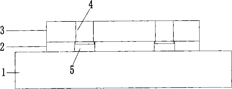
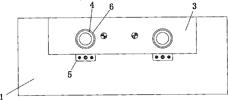
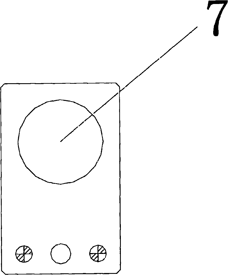
[0017] As shown in the figure, a quick-change guide sleeve fixing structure includes a mold base 1, a lower pad 2, a lower template 3, a guide sleeve 4 and a pad 5, and a lower pad 2 is arranged on the mold base 1. The mold base 1 is provided with an opening 9 larger than the diameter of the guide sleeve, and the lower block 2 is provided with a lower template 3, and the lower template 3 is provided with a through hole 6 for installing the guide sleeve 4, and the guide sleeve 4 is provided with a There is a T-shaped hanging table 8, and the T-shaped hanging table 8 is hung outside the bottom of the lower formwork 3. A groove is provided in the lower template 3 to facilitate the T-shaped hanging table 8 to pass through the groove. 2 is provided with a slot, and a spacer 5 is inserted into the slot, and a fixing hole 7 is provided on the spacer 5, and the two ends of the...


PUM


Abstract

The invention discloses a quick-change type guide sleeve fixing structure comprising a guide sleeve, a cushion block, a die holder, a lower cushion block and a lower template, the lower cushion block is arranged on the die holder, the lower template is arranged on the lower cushion block, and the lower template is internally provided with through holes for installing the guide sleeve; the invention is characterized in that the guide sleeve is provided with a T-shaped hanging boss which hangs outside the bottom of the lower template, the lower template is internally provided with a groove for the T-shaped hanging boss to penetrate through, the lower cushion block is provided with a notch, the cushion block is inserted into the notch to clamp the guide sleeve, and the die holder is internally provided with open holes with diameter larger than that of the guide sleeve. The invention solves the problems in the prior art that replacement time of glue pouring type guide sleeve after abrasion to influence normal production of enterprises and that the die with glue pouring type guide sleeve fixing structure has poor preciseness. The invention is convenient in operation, a new guide sleeve only needs about one hour to replace without needing to reassemble the die, and the structure is stable, thus being of greatly help to quality and production efficiency.

Description

technical field [0001] The invention relates to a guide sleeve fixing structure, in particular to a quick-change guide sleeve fixing structure. Background technique [0002] With the development of science and technology, guide sleeves have been widely used in the stamping industry. Guide sleeves are often used for drilling and boring. Generally, the ones used for drilling are called drill sleeves, and the ones used for boring are called tool bar guide sleeves. The tool rod will not deviate during cutting, so as to improve the dimensional accuracy and position accuracy of the processed hole. In the current stamping industry, the guide sleeve is fixed by pouring glue when assembling the mold. Because the guide sleeve is fixed in the plate with glue, the size of the inner hole on the plate and the size of the guide sleeve are matched by a clearance fit. , so the precision of the mold is low; and the mold stamping for a period of time, the guide sleeve will wear out, if you wa...

Claims


Application Information

Patent Timeline
Patent Type & Authority Applications(China)
IPC IPC(8): B21D37/12
Inventor 陈瑞益夏斌
Owner 皇裕精密技术(苏州)有限公司
Why Eureka
Try Eureka