Adjustable support of outdoor movable floor

A raised floor and adjustable technology, used in the field of building decoration materials, can solve the problems of small height adjustment range, inability to rain or high cost of fountain water recovery and maintenance, and achieve the effect of large height adjustment range

Inactive Publication Date: 2010-05-26
江苏汇东机房设备有限公司
View PDF0 Cites 1 Cited by
  • Summary
  • Abstract
  • Description
  • Claims
  • Application Information

AI Technical Summary

Problems solved by technology

[0002] The traditional paving of squares and parks is to directly fix the floor on the ground surface through cement and other adhesives. This paving method has the following disadvantages: first, the height adjustment range of the traditional paving method is too small; second, the traditional paving method The laying method is not conducive to the laying and maintenance of various cables and water conservancy pipelines. After the cables and water conservancy pipelines fail, the maintenance needs to destroy the laid floor. After the maintenance, the damaged ground must be repaired. The maintenance is complicated and the maintenance cost Too high. Third, the traditional laying method needs to lay special drainage pipes, and it is impossible to recycle rainfall or fountain water, which is not conducive to the recycling and reuse of water resources, resulting in waste of water resources, and the cost of laying drainage pipes is high , and the effect is not obvious. Fourth, if the floor is damaged, the cement bond on the floor needs to be cleaned up. Maintenance and repair are difficult, and the maintenance cycle is long, which also increases the maintenance cost virtually.

Method used


Image

  • Adjustable support of outdoor movable floor
  • Adjustable support of outdoor movable floor
  • Adjustable support of outdoor movable floor

Examples


Embodiment approach 1

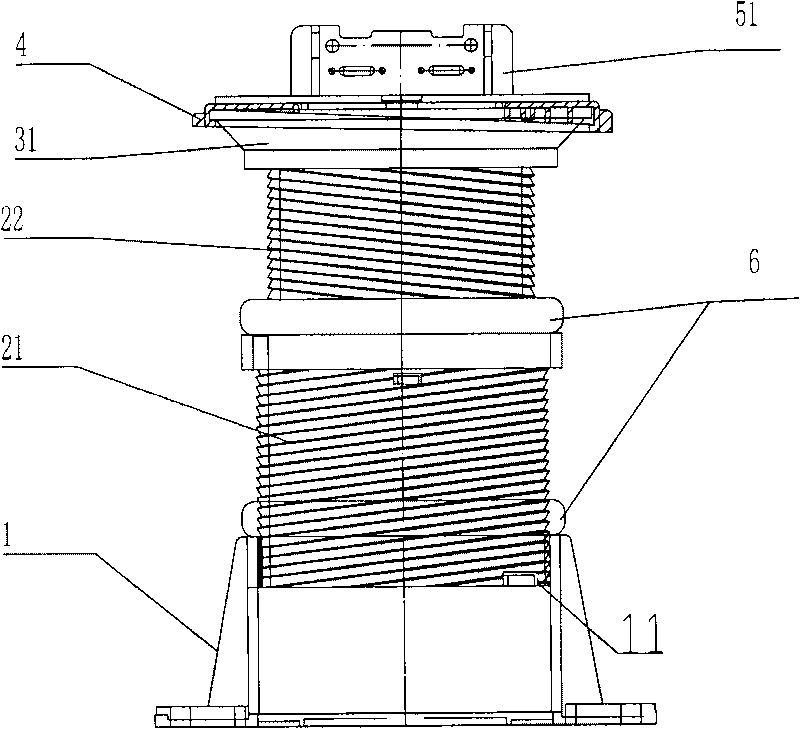
[0036] Implementation mode one: if figure 1 , 7 , 8, 11 and 12 described movable floor adjustable support, including base 1, the inner wall of base 1 is provided with screw thread, is connected with the connecting sleeve 2 that outer wall is provided with screw thread on base 1, and the top of connecting cover 2 is provided with tray 31 , the upper surface of the tray 31 is an inclined plane, the adjusting disc 4 is set on the tray 31, the lower surface of the adjusting disc 4 is an inclined plane with the same inclination angle as the upper surface of the tray 31, and the surrounding of the adjusting disc 4 is provided with a disc extending downward. Side 41, the inner side of disc side 41 is provided with protruding tooth 42, and adjustment disc 4 is sleeved on the tray 31, and adjustment disc 4 can rotate relative to tray 31, and protruding tooth 42 is stuck on the lower disc surface of tray 31, prevents adjustment disc 4 Falling off, through the cooperation of the upper s...

Embodiment approach 2

[0037] Implementation mode two: if figure 2 , Figure 5-8 , Figure 11-14 with Figure 17As shown in the movable floor adjustable bracket, the inner wall of the base 1 is provided with threads, the middle and upper part of the cylinder wall of the base 1 is provided with a base limit through hole 11, the outer wall and the inner wall of the lower connecting sleeve 21 are provided with threads, and the lower connecting sleeve 21 is provided with threads. The middle and upper part of 21 is also provided with the lower connecting sleeve limit through hole 212, the lower connecting sleeve 21 is screwed on the base 1, the lower end surface of the lower connecting sleeve 21 is provided with the lower connecting sleeve groove 210, and the lower connecting sleeve groove 210 The lower connection sleeve limit block 211 is provided, and the lower connection sleeve limit block 211 cooperates with the base limit through hole 11 to ensure the number of teeth of the screw thread of the lo...

Embodiment approach 3

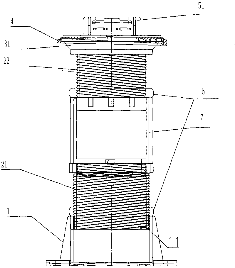
[0038] Implementation mode three: if image 3 with Figure 9-10 As shown in the movable floor adjustable bracket, an intermediate connecting sleeve 7 is connected between the upper connecting sleeve 22 and the lower connecting sleeve 21, the middle and upper part of the inner wall of the intermediate connecting sleeve 7 is provided with threads, and the bottom is also provided with an external thread connection part 71, the bottom end surface of the middle connecting sleeve 7 is provided with a groove, the groove is provided with a locking tooth 72, and at the same time, the upper end surface of the middle connecting sleeve 7 and the upper end surface of the lower connecting sleeve 2 are provided with several ribs 9, the middle The locking teeth of the connecting sleeve 7 are locked in the slots formed by the adjacent ribs 9 on the upper end surface of the lower connecting sleeve 2, and other connection methods are the same as those in the second embodiment. In addition, seve...


PUM


Abstract

The invention discloses an adjustable support of an outdoor movable floor laid on square or park surfaces, relating to the field of building and ornament materials. The adjustable support comprises a base and a connecting sleeve, wherein the inner wall of the base is provided with threads, the outer wall of the connecting sleeve is provided with threads, and the threads on the outer wall of the connecting sleeve are connected with the threads on the inner wall of the base. A tray is arranged on the top of the connecting sleeve, and an adjusting disk is connected with the tray. The lower surface of the adjusting disk and the upper surface of the tray are inclined surfaces with same tilt angles, and the adjusting disk can rotate relatively to the tray. The adjustable support has wide height adjusting range, adjustable levelness and locking function.

Description

technical field [0001] The invention and the field of building decoration materials particularly relate to an adjustable support for a raised floor used for paving the ground in squares or parks. Background technique [0002] The traditional paving of squares and parks is to directly fix the floor on the ground surface through cement and other adhesives. This paving method has the following disadvantages: first, the height adjustment range of the traditional paving method is too small; second, the traditional paving method The laying method is not conducive to the laying and maintenance of various cables and water conservancy pipelines. After the cables and water conservancy pipelines fail, the maintenance needs to destroy the laid floor. After the maintenance, the damaged ground must be repaired. The maintenance is complicated and the maintenance cost Too high. Third, the traditional laying method needs to lay special drainage pipes, and it is impossible to recycle rainfall...

Claims


Application Information

Patent Timeline
Patent Type & Authority Applications(China)
IPC IPC(8): E01C15/00
Inventor 孙世度张建华
Owner 江苏汇东机房设备有限公司
Why Eureka
Try Eureka