Emergency ballast system

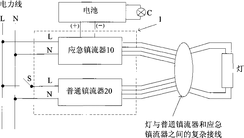
A technology of ballast and emergency power supply, which is applied in the field of emergency ballast system, and can solve problems such as lamp damage, complicated wiring, and high system cost

Inactive Publication Date: 2010-05-26
OSRAM GMBH
View PDF2 Cites 10 Cited by
  • Summary
  • Abstract
  • Description
  • Claims
  • Application Information

AI Technical Summary

Problems solved by technology

[0003] in such as figure 1 In the scheme shown, the wiring from the two ballasts to the lamp is very complex, resulting in a high probability of miswiring
In addition, the varying capacitance of the output wiring to the lamp unit can cause electromagnetic interference
Also, each type of lamp requires a dedicated emergency ballast to keep the lamp operating within its specifications (generic emergency ballasts will generally not keep the lamp working properly and will cause the lamp to fail faster)
In addition, the emergency ballast and the normal ballast each require an inverter for high-frequency operation of the lamp, making the system cost high
Furthermore, in this scheme, emergency ballasts are almost impossible to use in parallel with dimmable ballasts due to the high sensitivity to the capacitance of the wiring in dimmable applications

Method used


Image

  • Emergency ballast system
  • Emergency ballast system
  • Emergency ballast system

Examples


Embodiment Construction

[0011] Exemplary embodiments of the present invention will be described in detail below with reference to the accompanying drawings. In the interest of clarity and conciseness, not all features of an actual implementation are described in the specification. However, it should be understood that in proceeding with any such actual implementation, a number of implementation-specific decisions must be made in order to achieve the developer's goals, such as compliance with various system-related and business-related constraints , and these constraints vary across implementations. Moreover, it will be appreciated that such an implementation effort might be complex and time-consuming, but would nevertheless be a routine undertaking for those of ordinary skill in the art, given the present disclosure.

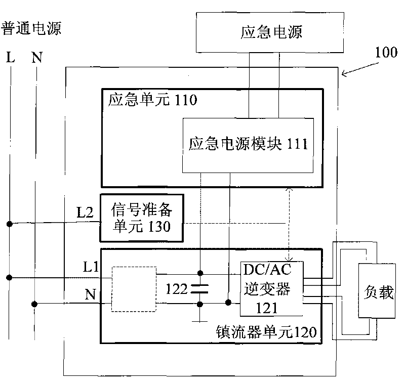
[0012] figure 2 An emergency ballast system 100 is shown in accordance with one embodiment of the present invention. The emergency ballast system 100 includes an emergency unit 110...


PUM


Abstract

The invention provides an emergency ballast system which comprises a ballast unit, a signal preparation unit and an emergency unit, wherein the ballast unit is provided with a DC/AC inverter and is used for supplying power to a load which is connected to the emergency ballast system when a common power supply works normally by using the common power supply; the signal preparation unit is connected to the common power supply and is used for detecting the working condition of the common power supply, generating a detection signal for reflecting the working condition of the common power supply and outputting the detection signal to the emergency unit; and the emergency unit comprises an emergency power supply module. When the common power supply has a fault, the emergency unit is used for responding to the detection signal for reflecting the fault, and an emergency power supply which is connected to the emergency unit is used for supplying power to the DC/AC inverter.

Description

technical field [0001] The present invention relates to emergency ballast systems. Background technique [0002] Current ballast systems for emergency lighting, such as that of fluorescent lighting fixtures, are often very complex. These systems often include an emergency ballast in addition to the normal ballast. figure 1 A prior art emergency ballast system 1 is shown. Such as figure 1 At any time, the emergency ballast system 1 includes an emergency ballast 10 and a normal ballast 20 . The wiring of the emergency ballast 10 and the normal ballast 20 on the output side allows the lamp to be fully switched from being powered by the normal ballast 20 to being powered by the emergency ballast 10 or from being powered by the emergency ballast 10 To be powered by common ballast 20 . In an emergency, the emergency ballast 10 utilizes the battery 30 to drive the lamp. In most cases, relays are used to achieve the above switching. [0003] in such as figure 1 In the soluti...

Claims


Application Information

Patent Timeline
Patent Type & Authority Applications(China)
IPC IPC(8): H05B41/46
CPCH05B37/0227H02J9/065H05B41/2983H05B47/105
Inventor 米谢勒·蒂索雷内·特瓦德齐克
Owner OSRAM GMBH
Why Eureka
Try Eureka