Dynamic umbilicals with internal steel rods

a technology of internal steel rods and umbilicals, applied in the direction of insulated conductors, power cables, cables, etc., can solve the problems of increased load applied to the umbilical, increased external diameter of the umbilical, and increased hydrodynamic load

Inactive Publication Date: 2002-10-29
TECH FRANCE SA
View PDF10 Cites 159 Cited by
  • Summary
  • Abstract
  • Description
  • Claims
  • Application Information

AI Technical Summary

Problems solved by technology

Electrical and / or optical fiber cables are not designed to resist the loads applied to the umbilical.
Since the S-Z configuration cannot withstand substantial tensile stress without unwinding, additional layers of armoring (steel or Kevlar, for example) must be wound counterhelically around this bundle.
However, under severe conditions (such as use in deep water and / or in dynamic applications), increased loads will be applied to the umbilical, due to the weight of the umbilical and to the dynamic movement of water.
This measure, however, leads to an increase in the external diameter of the umbilical and a corresponding increase in the hydrodynamic load (see for example cross-section E-3.7 in the API Specification).
They do not absorb any substantial tensile loading or increase the weight of the umbilical.
the manufacture of the umbilical becomes more difficult or even impossible.
the outer diameter of the umbilical increases, which leads to an increase in the hydrodynamic drag area.
the manufacturing cost increases, since an armoring machine is needed for the armor layers and the number of manufacturing passes is increased as well.

Method used


Image

  • Dynamic umbilicals with internal steel rods
  • Dynamic umbilicals with internal steel rods

Examples


Embodiment Construction

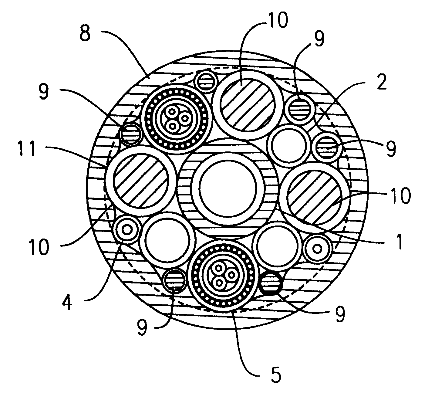
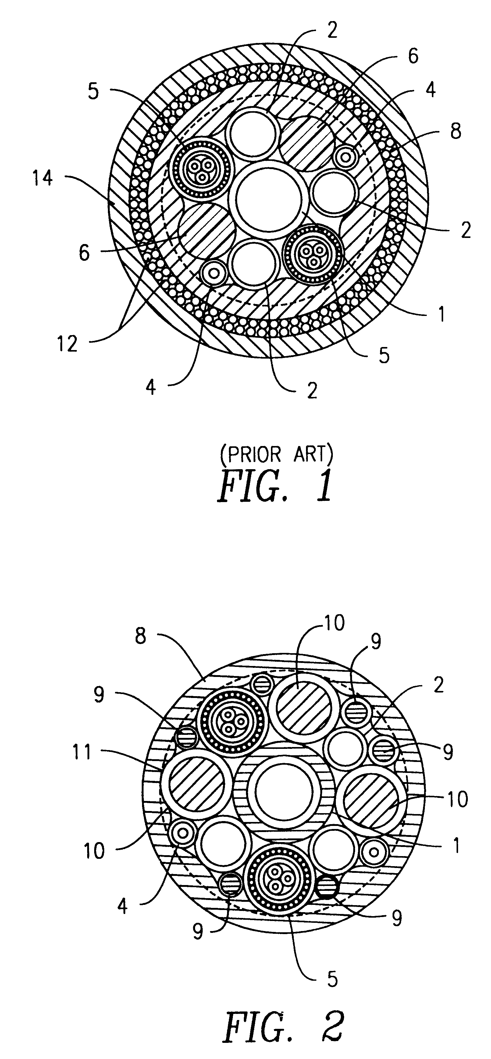
FIG. 2 is a cross-sectional view of a dynamic umbilical, for example for use as a riser, according to an embodiment of the invention. The respective fluid-carrying and other conduits in the umbilical of FIG. 2 correspond to those in FIG. 1. Unnecessary redundant description of those elements will be omitted.

In order to provide an improved, smaller umbilical for dynamic application, with excellent stability, high tensile resistance and fatigue resistance, the thermoplastic fillers in the umbilical of FIG. 1 have been replaced with three solid steel rods 10 which in this embodiment have a diameter of 20 mm. These steel rods are designed to absorb the tensile loading and to ballast the umbilical. In order further to increase the weight, small solid steel rods 9, which may be about 8 mm in diameter, are also added, in the periphery of the bundle. With this arrangement, the steel rods act as both tension and ballast elements and the need of an outer layer of armoring is avoided.

The steel...


PUM

PropertyMeasurementUnit
depthsaaaaaaaaaa
diameteraaaaaaaaaa
diameteraaaaaaaaaa

Abstract

In an umbilical, one or more steel rods, which provide strength and ballast, are wound helically within the umbilical along with the steel tubes and/or elongated active umbilical elements. These steel rods replace some or all of the thermoplastic filler elements that would otherwise be included within the umbilical. An umbilical according to an embodiment of the invention may include a plurality of steel tubes helically wound around a core, and at least one substantially solid steel rod helically wound around the core, the steel rod being arranged in a void between the steel tubes. Thus, the invention avoids the need to apply additional armoring layers to the outside of the umbilical for strength and ballast.

Description

1. Field of the InventionThe present invention relates to improvements in umbilicals, particularly steel umbilicals for use in dynamic applications such as in risers.2. Background ArtAn umbilical consists of a group of one or more types of elongated active umbilical elements, such as electrical cables, optical fiber cables, or hoses, cabled together for flexibility and over-sheathed and / or armored for mechanical strength and ballast.Umbilicals are used for transmitting power, signals and fluids (fluid injection, hydraulic power, gas release, etc.) to and from a subsea installation via the various elongated umbilical elements. An increasingly important use of umbilicals is the transmission of electrical power to electrical devices on the seabed, and depths of up to 6000 feet (2000 meters) are becoming common.Generally, the elements are arranged within the umbilical as symmetrically as possible. The cross-section is preferably circular. In order to fill the interstitial voids between ...

Claims


Application Information

Patent Timeline
Patent Type & Authority Patents(United States)
IPC IPC(8): H01B7/04H01B7/00H01B9/00
CPCH01B7/0072H01B7/045H01B9/003H01B9/005F16L11/22
Inventor DUPONT, WAYNERINEHART, RICHARDMCMANUS, JOHN
Owner TECH FRANCE SA
Why Eureka
Try Eureka