Multi-angular fastening apparatus and method for surgical bone screw/plate systems

a multi-angular, bone screw technology, applied in the field of multi-angular fastening apparatus and method for surgical bone screw/plate system, to achieve the effect of significant flexibility in practi

Inactive Publication Date: 2005-10-18
THE UNIV OF NORTH CAROLINA AT CHAPEL HILL
View PDF13 Cites 423 Cited by
  • Summary
  • Abstract
  • Description
  • Claims
  • Application Information

AI Technical Summary

Benefits of technology

[0006]The present invention in broad terms provides a plate or other component suitable for affixation by a fastener. The plate has one or more apertures through which one or more corresponding fasteners can be inserted. Notably absent from these apertures are any forms of permanent internal thread structures as found in the prior art and which, as indicated above, are a limitation in applications such as the treatment of bone trauma. Each aperture is bounded by a region structured to enable the fastener, and particularly a threaded head portion of the fastener, to be tapped into the material constituting the region. By providing this tappable region

Problems solved by technology

Notably absent from these apertures are any forms of permanent internal thread structures as found in the pr

Method used


Image

  • Multi-angular fastening apparatus and method for surgical bone screw/plate systems
  • Multi-angular fastening apparatus and method for surgical bone screw/plate systems
  • Multi-angular fastening apparatus and method for surgical bone screw/plate systems

Examples


Embodiment Construction

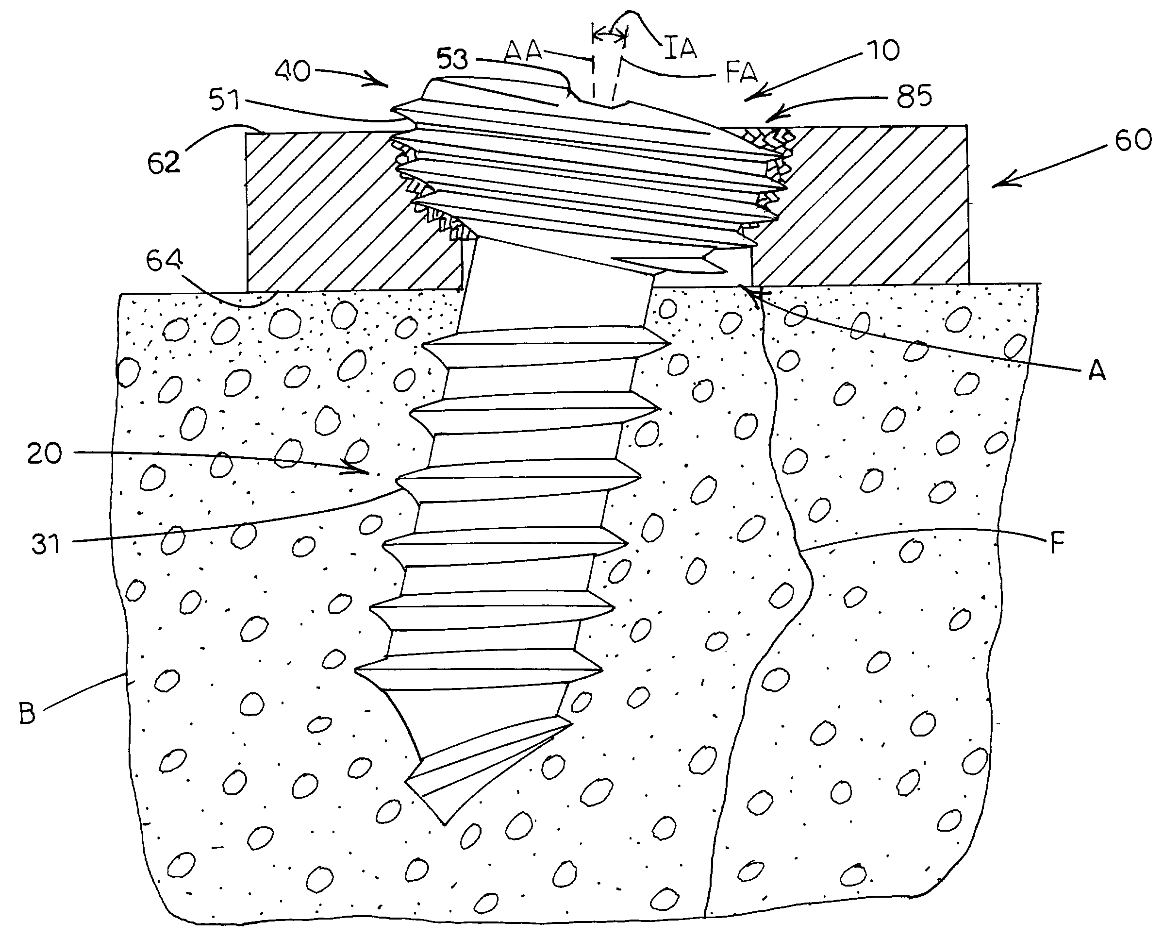
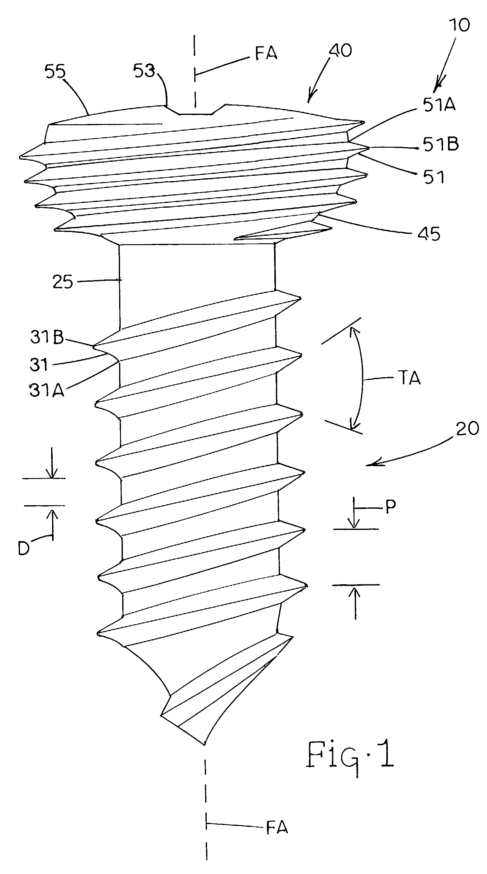
[0027]Referring now to FIG. 1, one example of a threaded-head fastener, generally designated 10, is illustrated in accordance with the present invention. Fastener 10 can be constructed from any material appropriate for withstanding compressive, tensile, torque, or other forces encountered during and after application of fastener 10 to a target site. In the context of orthopaedic surgery, fastener 10 is preferably constructed from a biocompatible metal or metal alloy such as stainless steel, titanium, chromium, or alloys thereof. As is appreciated by persons skilled in the art, fastener 10 could also be constructed from a suitable ceramic material or a polymeric material such as a resorbable polymer, or could be coated with a polymeric film. Fastener 10 comprises an elongate section, generally designated 20, and an adjoining head section, generally designated 40, both of which are generally arranged along a longitudinal fastener axis FA. Elongate section 20 comprises a shaft having a...


PUM


Abstract

A fastening apparatus includes a fastener and a fastener receiving member. The apparatus enables the fastener to be affixed to the fastener receiving member at a variable insertion angle selected by the user. The fastener includes an elongate section and an adjoining head section. Both the elongate section and the head section are threaded. The fastener receiving member includes one or more apertures through which one or more corresponding fasteners can be inserted. Each aperture includes a contact region formed or disposed on an inside surface defining the aperture. The contact region includes a porous matrix of protrusions or fiber metal having a density and strength sufficient to render contact region tappable by the thread of the head section of the fastener. The thread on the head section is driven into the contact region at the selected insertion angle. As a result, the thread of the head section taps into the material of the contact region such that the fastener is affixed to the fastener receiving member and maintained at the insertion angle.

Description

TECHNICAL FIELD[0001]The present invention relates generally to the design of fasteners and components to which fasteners are affixed. A specific application of the present invention relates to the design and use of bone screw / plate systems in the course of orthopaedic surgical procedures.BACKGROUND ART[0002]A variety of techniques exist in the field of orthopaedic surgery for treating bone fractures. Many known techniques utilize bone screws and bone fixation plates. Typically, the plate is used to stabilize the site of a bone fracture, and one or more bone screws are inserted through apertures of the plate and threaded into the bone material so as to secure the plate to the bone material. It is also known that bone screw / plate systems can be improved by machining a thread onto the head of the bone screw, in addition to the thread normally machined onto the main shaft of the screw. In connection with the use of threaded-head screws, the apertures of the plate are threaded to mating...

Claims


Application Information

Patent Timeline
IPC IPC(8): A61B17/68A61B17/80A61B17/86
CPCA61B17/8057A61B17/8605A61B17/863
Inventor DAHNERS, LAURENCE E.
Owner THE UNIV OF NORTH CAROLINA AT CHAPEL HILL
Why Eureka
Try Eureka