Method and apparatus for transmit beamformer system

a beamformer and transmit beam technology, applied in the field of coherent imaging systems, can solve the problems of undetectable transientity, and inability to achieve optimal transmission,

Inactive Publication Date: 2002-03-26
ACUSON
View PDF74 Cites 126 Cited by
  • Summary
  • Abstract
  • Description
  • Claims
  • Application Information

AI Technical Summary

Benefits of technology

The digital transmit beamformer has a high degree of programmability. In particular, pulse shape can be programmed by assignment of appropriate initial waveform samples to each transmit processor; carrier frequency is also a programmable parameter, as are per-transmit-channel delay and apodization values. Arbitrary delay correction values, additional to the above delay values and computed by external equipment to adjust for aberration and calibration effects, can also be programmed for each transmit channel.
Because of the above parameterization of transmit waveforms, extensive flexibility is achieved without incurring the problems associated with the direct implementation approach described above. Additionally, the amount of information which must be specified to each transmitter in order to produce a desired composite beam response by firing the ultrasonic transducer array is substantially reduced compared to that of the direct implementation approach. Thus, for PW operation, pulse waveform parameters can be specified to the transmit beamformer on a per transmit channel and per firing basis, without degrading the scan frame rate to non-useful diagnostic levels. Waveform parameters can be specified to the transmitters by an external central control system (see above-cited METHOD AND APPARATUS FOR FOCUS CONTROL OF TRANSMIT AND RECEIVE BEAMFORMER SYSTEMS co-pending patent application) which is responsible for higher level flexibility, such as scan formats, focusing depths and fields of view; thus the parameterization permits each transmitter to concern itself with only the generation of a single output pulse waveform.
When producing multiple transmit beams, each transmitter preferably processes its multiple waveforms in an interleaved manner using shared processing resources to a point in the signal path at which they are summed to generate the composite waveform that will generate multiple beams when combined with the composite waveforms produced by the other transmitters. Prior to that point in the signal path, the transmitter is operable in any of several predefined processing modes. The available processing resources preferably define processing modes with different parameter sets in a computational efficiency trade-off among (1) the maximum number of beams; (2) the initial waveform sampling rate (related to the maximum transmit bandwidth); and (3) transmit frequency (more precisely, the nominal center frequency F.sub.0). The trade-offs provided by the available processing modes permit maximum usage of the available computational capacity of the hardware.

Problems solved by technology

However, such versatility can undesirably require extensive hardware resources if carried out in a direct implementation.
Little effort, however, has been made to improve the characteristics of transmit beam formation.
The envelope shape of a pulse waveform was otherwise essentially fixed, and due to the limitations of analog processing, was not optimal.
Simultaneous satisfaction of all these objectives cannot be obtained using presently available ultrasonic transmit beamformers.
The techniques used in these test instruments are generally not applicable or practical for phased array ultrasonic transmit beamforming, however, and in any event, have not been used for that purpose.
For example, they could support only a single transmit channel and could not perform beamforming, in part because of cost, power and space constraints.
While such a system could be built and could achieve the desired objectives, it is impractical with current technology for several reasons.
First, a large amount of memory would be required, and it would have to operate at very high data rates.
Second, assuming an aspect of the desired flexibility includes the flexibility to alter the waveforms in real time prior to each firing, then the amount of computations required to compute each waveform, and the amount of time required to download all of the waveform samples into the memory, would reduce the scan frame rate to levels which are not diagnostically useful.

Method used


Image

  • Method and apparatus for transmit beamformer system
  • Method and apparatus for transmit beamformer system
  • Method and apparatus for transmit beamformer system

Examples


Embodiment Construction

1. Digital Multichannel Transmit Processor Digital Signal Processing

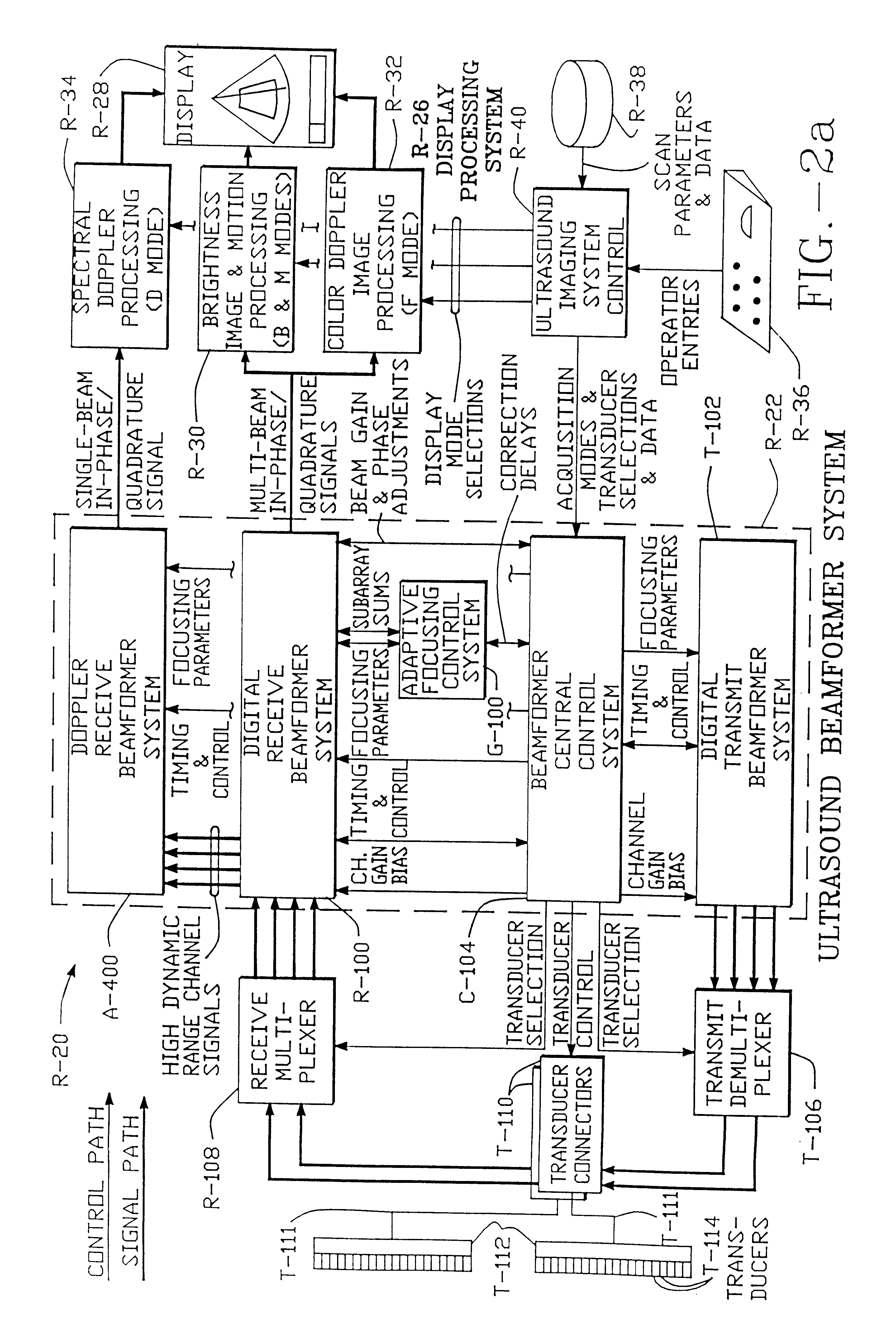
In the preferred embodiment, the transmit beamformer T102 includes a substantially independent waveform generating processor for each transmit element. Transmit processors T104 are referred to herein as multichannel processors because each of the individual transmit processors can provide multiple, programmable complex envelope waveform generation. A substantially continuous range of imaging frequencies is supported.

Overall, each transmit processor performs the primary functions of (1) waveform shaping of one or more waveforms for one or more beams, (2) apodization, and (3) insertion of steering / focusing time delays for such waveforms. To perform waveform shaping for a PW transmission, the signal path begins with initial waveform samples at a rate R.sub.E below that of the DAC T121 sampling frequency F.sub.s. The initial waveform samples can have a frequency spectrum centered at 0 Hz, or can be offset from 0 Hz. Wav...


PUM

PropertyMeasurementUnit
frequenciesaaaaaaaaaa
frequency spectrumaaaaaaaaaa
frequenciesaaaaaaaaaa

Abstract

A digital transmit beamformer system with multiple beam transmit capability has a plurality of multi-channel transmitters, each channel with a source of sampled, complex-valued initial waveform information representative of the ultimate desired waveform to be applied to one or more corresponding transducer elements for each beam. Each multi-channel transmitter applies beamformation delays and apodization to each channel's respective initial waveform information digitally, digitally modulates the information by a carrier frequency, and interpolates the information to the DAC sample rate for conversion to an analog signal and application to the associated transducer element(s). The beamformer transmitters can be programmed per channel and per beam with carrier frequency, delay, apodization and calibration values, For pulsed wave operation, pulse waveform parameters can be specified to the beamformer transmitters on a per firing basis, without degrading the scan frame rate to non-useful diagnostic levels. Waveform parameters can be specified to the transmitters by an external central control system which is responsible for higher level flexibility, such as scan formats, focusing depths and fields of view. The transmit pulse delay specified per-channel to each transmitter is applied in at least two components: a focusing time delay component and a focusing phase component. The carrier frequency can be specified for each transmit beam, to any desired frequency within a substantially continuous predefined range of frequencies, and a beam-interleaved signal processing path permits operation in any of several predefined processing modes, which define different parameter sets in a trade-off among (1) the number of beams produced; (2) per-beam initial waveform sample interval; and (3) transmit frequency.

Description

REFERENCE TO MICROFICHE APPENDIXThis application includes a microfiche appendix of 195 sheets of microfiche having 19,058 frames. A portion of the disclosure of this patent document contains material which is subject to copyright protection. The copyright owner has no objection to the facsimile reproduction by any one of the patent disclosure, as it appears in the Patent and Trademark Office patent files or records, but otherwise reserves all copyright rights whatsoever.1. Field of the InventionThis invention relates to coherent imaging systems including, for example, radar, sonar, seismic, and ultrasound systems, using vibratory energy, and in particular, but not limited to, phased array ultrasound imaging systems for scan formats such as linear, steered linear, sector, circular, Vector.RTM., steered Vector.RTM. and other types of scan formats in imaging modes such as, by way of example only, B-mode (gray-scale imaging mode), F-mode (flow or color Doppler imaging mode), M-mode (mot...

Claims


Application Information

Patent Timeline
Patent Type & Authority Patents(United States)
IPC IPC(8): G01S15/89G01S15/00G01S7/52G10K11/34G10K11/00G01N29/44A61B8/00G01N29/24G01S7/523G03B42/06
CPCG01S7/52017G01S7/52026G01S7/52046G01S7/52066G01S15/8915G01S7/52095G01S15/8979G01S15/8988G10K11/341G10K11/345G01S7/5209G01S7/52028G01S7/52049
Inventor COLE, CHRISTOPHER R.GEE, ALBERTLIU, THOMAS
Owner ACUSON
Why Eureka
Try Eureka