Wireless network control for building lighting system

a wireless network control and building lighting technology, applied in the field of electrical energy control, can solve the problems of inflexible to changing requirements in the workplace, inability to respond to available daylight or occupancy, and high installation cost of traditional wired switches

Active Publication Date: 2009-11-24
RGT UNIV OF CALIFORNIA
View PDF43 Cites 157 Cited by
  • Summary
  • Abstract
  • Description
  • Claims
  • Application Information

AI Technical Summary

Problems solved by technology

In many buildings, much of this energy use is a result of lighting that is on unnecessarily because of inadequate controls.
Traditional wired switches are expensive to install, inflexible to changing requirements in the workplace, and unable to respond to available daylight or occupancy.
For example, many buildings have adequate daylight along the perimeter, but the installed switching is not adequate to turn off the unnecessary lights.
Available residential systems tie a specific switch to a specific relay or relay channel and do not provide the flexibility needed for commercial building applications.
Commercial systems require that specialized ballasts be installed to replace existing ballasts making them expensive and unlikely to gain significant market share.

Method used


Image

  • Wireless network control for building lighting system
  • Wireless network control for building lighting system
  • Wireless network control for building lighting system

Examples


Embodiment Construction

[0014]The embodiments of the present invention are directed to a wireless controller and a wireless network using the controller for the control of lighting systems. The radio-controlled device includes several novel features. In addition, a control system that integrates several sensors in a radio network to control lights using the radio-controlled device also includes various novel features. Each of these is described below in further detail.

Radio-controlled Relay Device

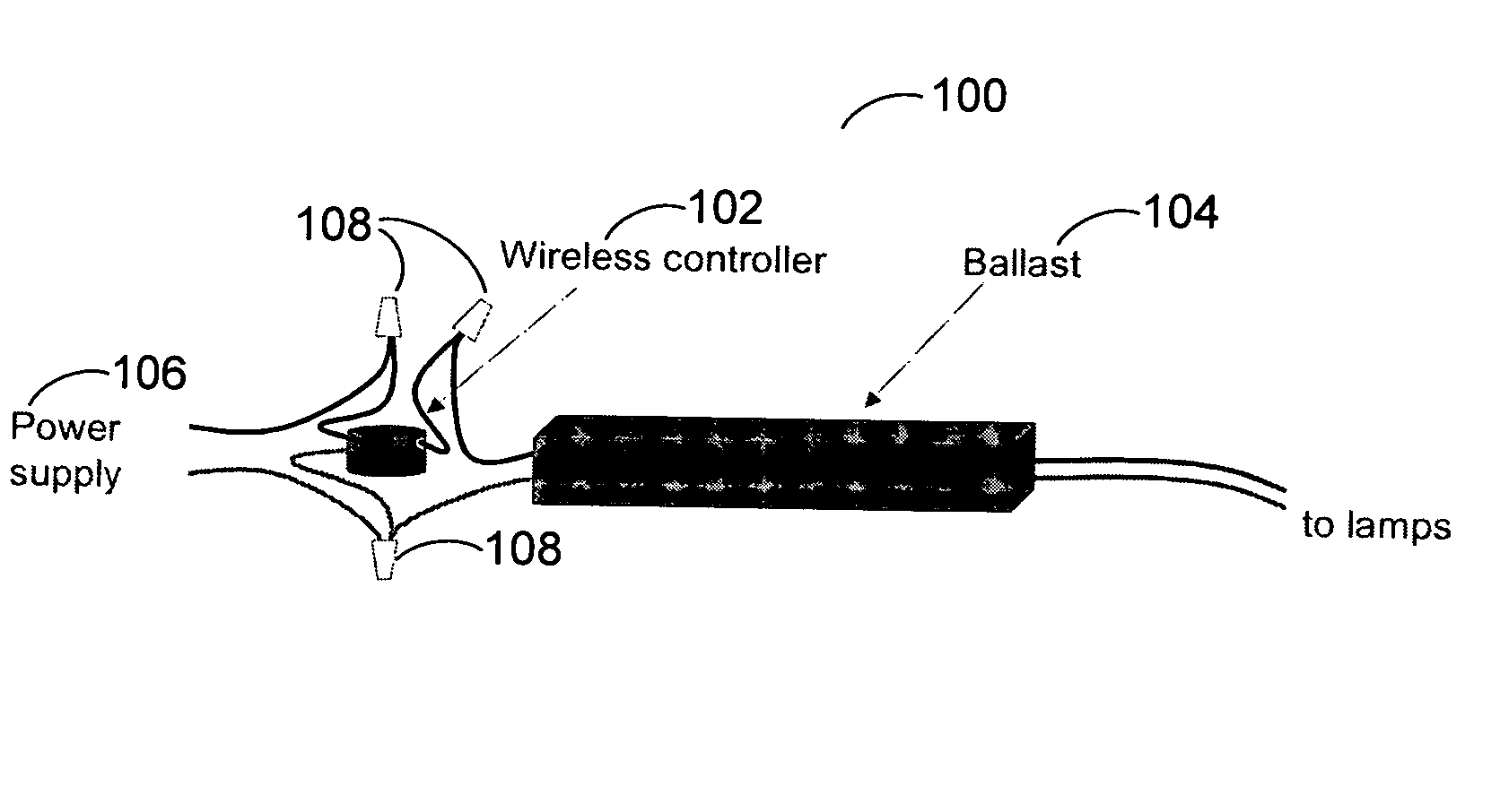
[0015]FIG. 1 is an exemplary schematic diagram 100 of a wireless controller controlled relay installation in accordance with one embodiment of the present invention. The radio-controlled relay device 102 can integrate a wireless radio, a relay (or one or more relays), a microprocessor, a dimming device, a power sensor and a signal generator in a stand-alone package that can easily be installed in a typical fluorescent fixture. It can be installed between ballast 104 and the ballast power source106 and is powered b...


PUM


Abstract

Wireless control of lighting fixtures via a wireless radio network using a radio-controlled relay device located between a lighting fixture or a ballast of a fluorescent fixture and its power supply. The radio-controlled device receives signals from remote controllers or via a computer interface. The wireless device is also configured to monitor the power consumption of a lighting fixture (or ballast) and send that information to the network. In the wireless control network, light level sensors and motion sensors also send information to the network to allow lights to respond to daylight levels or occupancy.

Description

CROSS-REFERENCES TO RELATED APPLICATIONS[0001]This application claims priority to U.S. Provisional Patent Application No. 60 / 661,714, filed Mar. 14, 2005, the disclosure of which is hereby incorporated by reference herein in its entirety for all purposes.BACKGROUND OF THE INVENTION[0002]The present invention relates in general to electrical energy control. In particular, the present invention relates to a wireless lighting controller for building lighting systems.[0003]Lighting energy accounts for nearly 40% of commercial building electricity consumption. In many buildings, much of this energy use is a result of lighting that is on unnecessarily because of inadequate controls. Traditional wired switches are expensive to install, inflexible to changing requirements in the workplace, and unable to respond to available daylight or occupancy. For example, many buildings have adequate daylight along the perimeter, but the installed switching is not adequate to turn off the unnecessary li...

Claims


Application Information

Patent Timeline
Patent Type & Authority Patents(United States)
IPC IPC(8): G08B21/00
CPCH01H47/24H04Q9/00H05B37/0218H05B37/0272H01H2300/03H04Q2209/82Y02B20/46Y02B90/224Y04S20/14H04Q2209/40H05B47/11H05B47/19Y02B20/40Y02B90/20H05B47/115
Inventor HUIZENGA, CHARLES A.
Owner RGT UNIV OF CALIFORNIA
Why Eureka
Try Eureka