Voltage regulating devices in LED lamps with multiple power sources

Active Publication Date: 2011-03-10
DENOVO LIGHTING
View PDF23 Cites 146 Cited by
  • Summary
  • Abstract
  • Description
  • Claims
  • Application Information

AI Technical Summary

Benefits of technology

[0026]An LED lamp device is disclosed primarily for the replacement of fluorescent lamps. The LED lamp contains circuitry to allow it to be used with multiple power sources providing versatility to the end user, and reducing material and inventory costs. The LED lamp terminates primarily in G13 bi-pins on opposing end caps. However, other pin terminating lamp bases will be possible to mate with the di

Problems solved by technology

This is not desirable in a lamp illumination system.
However, it doesn't disclose voltage reducing devices to protect the electrical com

Method used


Image

  • Voltage regulating devices in LED lamps with multiple power sources
  • Voltage regulating devices in LED lamps with multiple power sources
  • Voltage regulating devices in LED lamps with multiple power sources

Examples


first embodiment

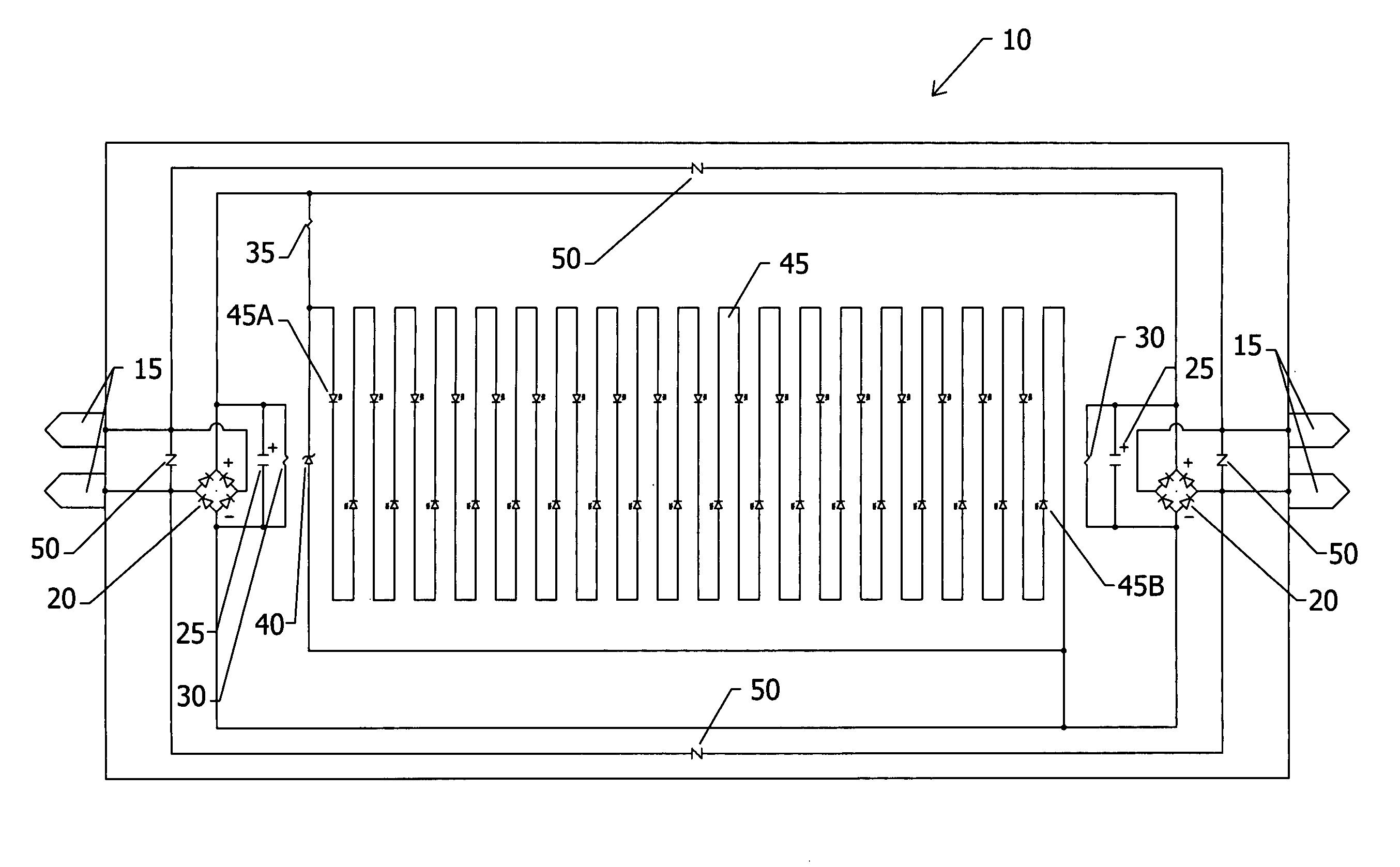
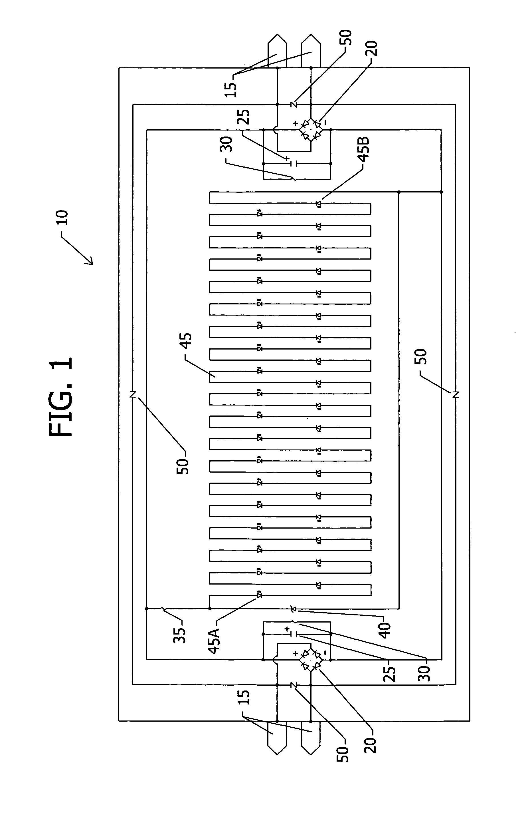
[0059]FIG. 1 shows the present invention using a high power current limiting resistor 35 and a zener diode 40 as the main voltage regulating device to provide power to a series string of LEDs 45. LED lamp 10 is shown with bi-pins 15 on opposite ends of LED lamp 10. On both ends, bi-pins 15 are connected to the AC sides of AC-to-DC converters 20. The positive sides of AC-to-DC converters 20 are connected together. The positive sides are also filtered through capacitors 25 and bleeder resistors 30, and then passes through high power current limiting resistor 35 connected in series with zener diode 40 and series string of LEDs 45. Voltage reducing devices 50 may be connected to the bi-pins 15 of LED lamp 10.

[0060]The actual AC-to-DC converter 20 used is a full-wave bridge rectifier. The bridge rectifier circuit can consist of four separate silicon diodes or one bridge component. This bridge rectifier results in a rippled DC current and therefore serves as an example circuit only. A dif...

second embodiment

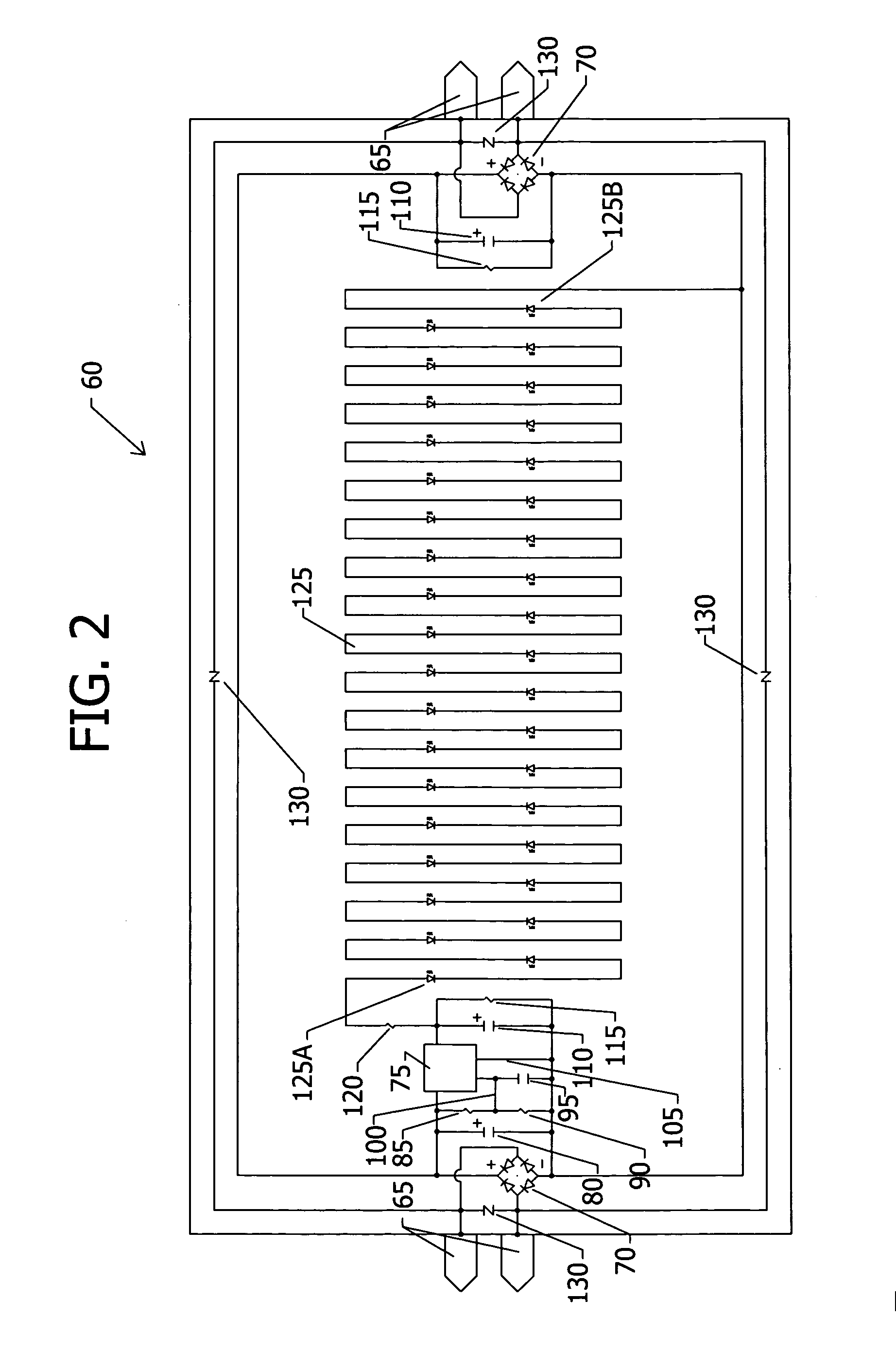
[0066]FIG. 2 shows the present invention using a high voltage regulator IC 75 as the main voltage regulating device to provide power to a series string of LEDs 125. LED lamp 60 is shown with bi-pins 65 on opposite ends of LED lamp 60. On both ends, bi-pins 65 are connected to the AC sides of AC-to-DC converters 70. The positive sides of AC-to-DC converters 70 are connected together. The positive sides of AC-to-DC converters 70 are also connected to a smoothing capacitor 80 and then to a resistor bridge consisting of resistor 85 and resistor 90. The positive sides of AC-to-DC converters 70 connect to one side of resistor 85 and to the input voltage side of high voltage regulator IC 75. The other side of resistor 85 is connected to one side of resistor 90 to base pin 100 of high voltage regulator IC 75 and to one side of capacitor 95. The other side of capacitor 95 connects to the negative sides of AC-to-DC converters 70 and to ground pin 105 of high voltage regulator IC 75. The outpu...

third embodiment

[0087]FIG. 5 shows the present invention using a high power current limiting resistor 280 and back-to-back zener diodes 285 as the main voltage regulating device to provide power to a series string of anti-parallel diode pairs 290. LED lamp 270 is shown with bi-pins 275 on opposite ends of LED lamp 270. Voltage reducing devices 300 may be connected to the bi-pins 275 of LED lamp 270.

[0088]The actual voltage reducing device 300 used is a varistor. A varistor or similar fusing device may be used to ensure that voltage is limited during power surges. The actual back-to-back zener diodes 285 can also be a back-to-back avalanche breakdown diodes or back-to-back TVS. Each anti-parallel diode pair 290 can consist of one diode and one LED, or both diodes can be LEDs. LED lamp 270 shows two LEDs in each anti-parallel diode pair 290. It will be noted that the LED lamp 270 will still operate with input power at only one end or across any two pins on bi-pins 275.

[0089]When ballast power is conn...


PUM


Abstract

LED driver circuits containing voltage reducing devices, voltage regulating devices, and voltage converting devices are disclosed as the main components to provide power to LEDs. The LED driver circuits are designed to work with a ballast, mains alternating current voltage, direct current voltage, and electromagnetic induction power. The voltage regulating devices can be a resistor in series with at least one zener diode or a voltage regulator both in parallel with and providing power to the LEDs. The LEDs can also be anti-parallel diode pairs consisting of one diode and one LED or two LEDs, or the LEDs can be anti-parallel diode string pairs consisting of diodes and LEDs or all LEDs. The LED driver circuits will be incorporated into LED replacement lamps, and in particular to LED lamps to replace fluorescent lamps for use with existing ballasts and other power sources where the ballast may be removed or bypassed.

Description

RELATED PRIORITY APPLICATION[0001]This application claims the benefit of priority of U.S. Provisional Application No. 61 / 276,095, filed on Sep. 8, 2009 and entitled, “Voltage Regulating Devices in LED Lamps with Multiple Power Sources”, the entirety of which is incorporated herein by reference.Field of the Invention[0002]The present invention relates to driver circuits for light emitting diode illumination lamp devices powered by different types of power sources.BACKGROUND OF THE INVENTION[0003]There are many LED retrofit and replacement lamps in the market today. In particular, linear LED lamps are becoming more available by different manufacturers to replace fluorescent lamps using existing lampholders in fixtures. There are LED lamps that are powered by existing ballasts. There are LED lamps that are powered by direct line alternating current voltage mains power where the ballast and starter if present is bypassed or removed. There are LED lamps that are powered by a DC power sup...

Claims


Application Information

Patent Timeline
IPC IPC(8): H05B37/02
CPCY02B20/386H05B33/0809H05B45/375Y02B20/30
Inventor KIT, JOHNHSU, GEORGIANA
Owner DENOVO LIGHTING
Why Eureka
Try Eureka