Bifilar-returning automatic control escape device for tall building

An escape device and high-rise technology, applied in the field of escape devices, can solve the problems of inability to achieve double-line round-trip up and down movement, missing the first time to escape, affecting the escape speed, etc. Effect

Inactive Publication Date: 2011-07-20
李良友
View PDF0 Cites 0 Cited by
  • Summary
  • Abstract
  • Description
  • Claims
  • Application Information

AI Technical Summary

Problems solved by technology

And although the existing known escape tools such as oblique rope slide, hanging blue or air cushion are safe and simple, they can play a certain life-saving effect, but these tools must be used after ambulance personnel receive the alarm and rush to the scene. It cannot be used alone before the arrival of ambulance personnel, which misses the first time of escape, and cannot save itself, increasing the chance of casualties
[0003] The applicant's invention patent "high-rise escape device (patent number: 2004100672306)" has the ability to make escapers slide down safely and at a uniform speed, and escape from danger in the first time to achieve the purpose of self-rescue. It has the advantages of reducing casualties caused by suffocation and crowding due to thick smoke, small size, ingenious force, safety and reliability, etc., but it can only do single-phase movement, and cannot realize double-line back and forth movement, which affects the escape speed, and only one at a time It is far from enough when the situation is extremely critical, and other people who will not be able to evacuate in the future will die because their lives are in danger.

Method used


Image

  • Bifilar-returning automatic control escape device for tall building
  • Bifilar-returning automatic control escape device for tall building
  • Bifilar-returning automatic control escape device for tall building

Examples


Embodiment Construction

[0018] The present invention will be described in further detail below in conjunction with the embodiments and with reference to the accompanying drawings.

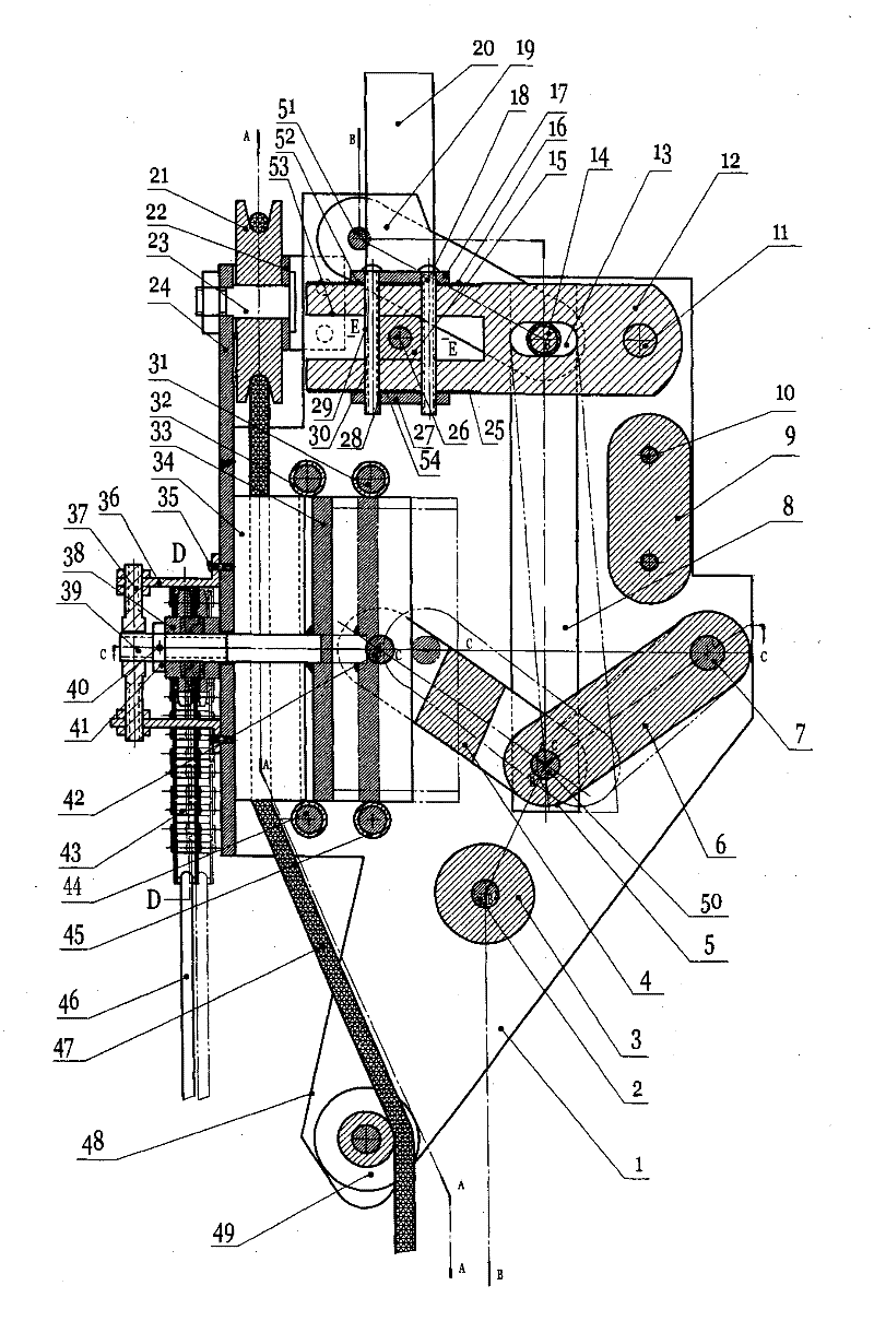
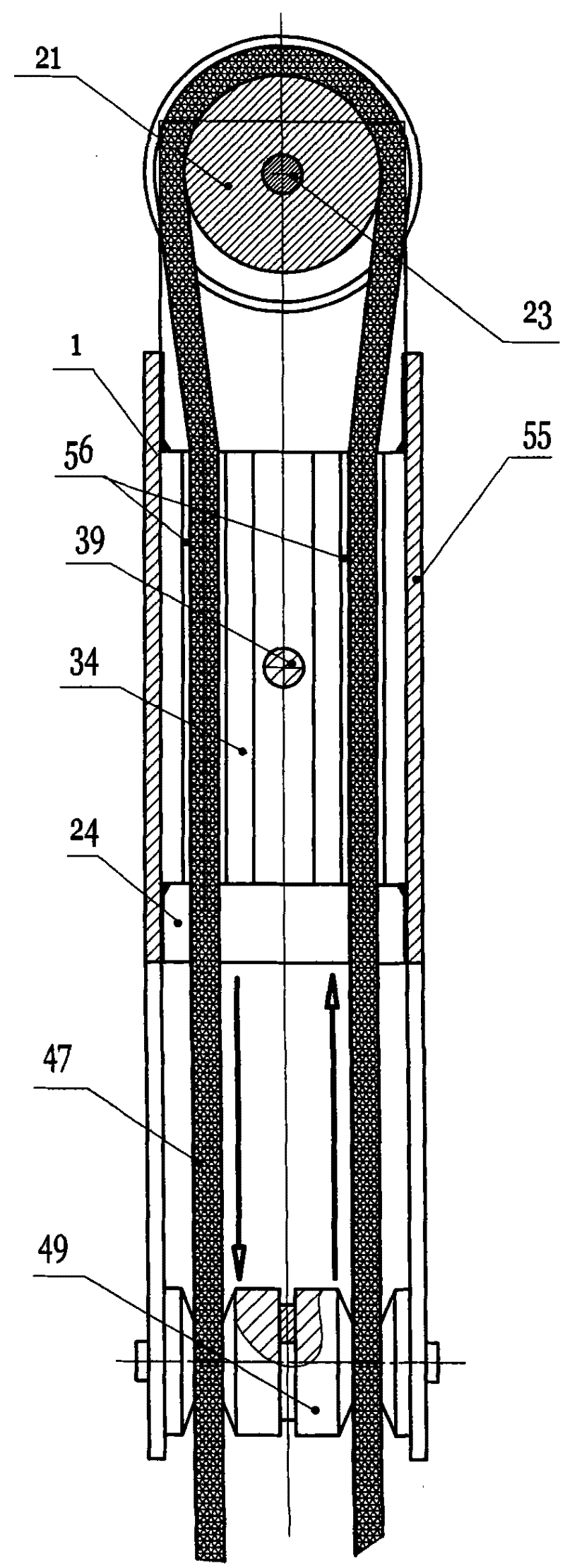
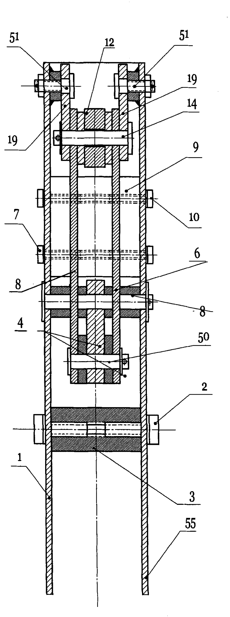
[0019]The present invention comprises hanging ring 20, rope 47, box body 48 and safety rope cover 58, and the top of hanging ring 20 is fixed on the ceiling in the house, window or fire exit fixed frame, and box body 48 is made of front box board 55, rear box Plate 1 and side box plate 24 are formed, and side box plate 24 is fixed between the left end of front box plate 55 and the left end of rear box plate 1, the bottom end, right end of front box plate 55 and the bottom end, right end of rear box plate 1 Respectively fixed together by the bottom connecting shaft 2 and the right connecting shaft 10, two ends are installed at the bottom between the front box plate 55 and the rear box plate 1 in the box body 48 to allow the two ends of the rope 47 to slide through and run respectively. The center of gravity wheel 49 that i...


PUM


Abstract

The invention discloses a bifilar-returning automatic control escape device for a tall building, comprising a hanging ring, ropes, a box body and safe rope slings. The device is characterized in that a reinforcing connecting rod consists of a left connecting rod and a right connecting rod, and the left end of the left connecting rod is moveably installed in a moveable friction groove; a sliding groove is processed in the middle of a lever, and the right end of a balance arm and the top end of a tension rod are sheathed in the sliding groove together; a fixed pulley is fixed between a lateral boxboard and a supporting frame; two fixed friction grooves through which both ends of each rope can penetrate are formed between a moveable friction member and a fixed friction member, and the two fixed friction grooves are separated from each other; the right end of the screw rod is fixedly installed in the middle of the moveable friction member, and the left end is installed in the middle of anadjusting screw rod; and a safe rope sling is respectively hung on the two lower ends of each rope. By adopting bifilar-returning up-and-down movement, the device accelerates the escape speed of an escaper, greatly improves the self rescue efficiency, reduces casualties caused by dense smoke suffocation and crowding, has high safety, reliability, and the like, and can be arranged on a clearly visible place in a tall building to meet an emergency.

Description

technical field [0001] The invention relates to an escape device, in particular to a two-line back-and-forth self-controlled escape device for a high-rise building. Background technique [0002] With the development of society, the number of high-rise buildings in the city has increased sharply, and the residential buildings have gradually become high-rise. This will inevitably bring about a public safety problem. event of particular concern. Due to the lack of escape equipment, the survivors were unable to escape in time, and they were either choked to death by the thick smoke, or fell or fell to death by jumping off the building. The annual casualties are particularly heavy and shocking. And although the existing known escape tools such as oblique rope slide, hanging blue or air cushion are safe and simple, they can play a certain life-saving effect, but these tools must be used after ambulance personnel receive the alarm and rush to the scene. It cannot be used alone be...

Claims


Application Information

Patent Timeline
Patent Type & Authority Patents(China)
IPC IPC(8): A62B1/06
Inventor 李良友李水李洲
Owner 李良友
Why Eureka
Try Eureka