Fire water monitor head for performing direct current spray conversion by adopting hydraulic drive

A technology of hydraulic drive and water cannon, applied in fire rescue and other directions, can solve the problems of small scope of application of the conversion mechanism, jamming, increase in the volume of the gun head, etc., and achieve the effect of eliminating the complexity of the mechanism and the large volume

Inactive Publication Date: 2010-06-02
EAST CHINA JIAOTONG UNIVERSITY
View PDF1 Cites 2 Cited by
  • Summary
  • Abstract
  • Description
  • Claims
  • Application Information

AI Technical Summary

Problems solved by technology

Utility model patent 200420082699.2 discloses an integral liquid-controlled DC-spray fire monitor nozzle. This patent adopts the form of a built-in sliding nozzle and combines the telescopic hydraulic cylinder with the sliding nozzle. Although the overall structure is relatively compact, due to the need for An additional hydraulic oil source is used to provide power, and a hydraulic control device is required to drive the hydraulic cylinder, so the conversion mechanism has a small scope of application and can only be used for hydraulic-controlled fire monitors
The fire water monitor head that converts DC spray through electric control is generally realized by driving a mechanical transmission mechanism with an AC motor or a stepping motor. Due to the mechanical transmission device in the driving mechanism, there will be mechanical impact during the transmission process. Due to the force Unevenness is easy to cause jamming, and the volume of the entire gun head will increase accordingly

Method used


Image

  • Fire water monitor head for performing direct current spray conversion by adopting hydraulic drive
  • Fire water monitor head for performing direct current spray conversion by adopting hydraulic drive

Examples


Embodiment Construction

[0011] Below in conjunction with accompanying drawing and embodiment the present invention will be further described:

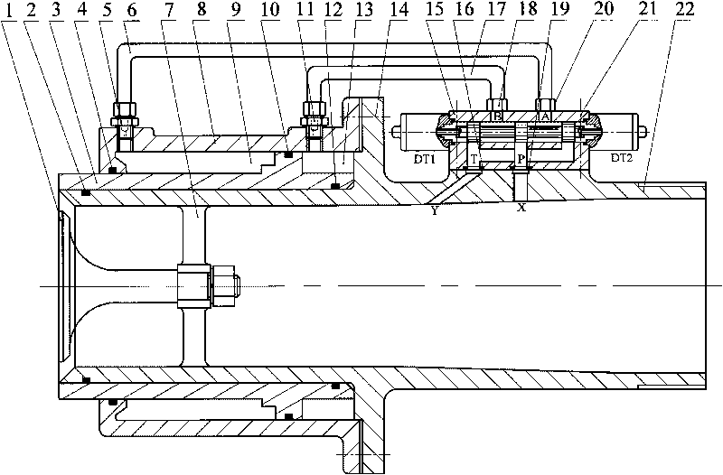
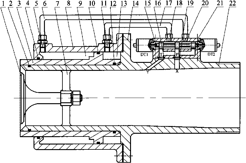
[0012] as attached figure 1 Shown, the present invention comprises nozzle core 1, sealing ring 2,4,10,12, nozzle 3, pipe joint I 5, water delivery hose I 6, nozzle core frame 7, cylinder body 8, left water pressure chamber 9, Pipe joint II 11, right water pressure chamber 13, fastening bolt 14, three-position four-way pure water electromagnetic reversing valve 15, sealing gaskets 16, 19, water hose II 17, pipe joint III18, pipe joint IV 20, Countersunk screw 21, nozzle housing 22.

[0013] The nozzle core 1 is fixed on the nozzle core frame 7 by a washer and a lock nut; the inner wall of the nozzle 3 forms a clearance fit with the outer wall of the nozzle housing 22, and the outer wall of the nozzle 3 forms a clearance fit with the inner wall of the cylinder body 8, and the nozzle 3 can Slide back and forth along the axial direction of the nozzle housing 22...


PUM


Abstract

The invention discloses a fire water monitor head for performing direct current spray conversion by adopting hydraulic drive, which comprises a nozzle shell, a nozzle, a nozzle core, a nozzle core rack, a cylinder body, a pipe joint, a water delivery hose, a three-position four-way pure water electromagnetic directional valve, a seal ring and the like. The fire water monitor head uses the most common pressure water in a fire-extinguishing scene as a power source, and is operated through conductive driving valve cores of electromagnets at the left end and the right end of the three-position four-way pure water electromagnetic directional valve to pressurize a left water pressure cavity and a right water pressure chamber of the nozzle respectively so that the nozzle slides back and forth to realize the automatic smooth conversion between direct current injection and spray injection for the fire water monitor head. By adopting the hydraulic drive directly, the fire water monitor head overcomes the defects of complex mechanism and large volume when a hydraulic control telescopic cylinder or an electric control driving mechanism is adopted to realize the direct current spray conversion at present. The fire water monitor head namely a conversion device has a simple and compact structure, is convenient to operate, and is particularly suitable for the occasions in need of achieving various functions such as fire distinguishing, cooling, diluting, protecting and the like during fire fighting.

Description

technical field [0001] The invention relates to a nozzle of a fire-fighting water monitor, in particular to a nozzle of a fire-fighting water monitor which adopts hydraulic drive to convert direct-current spraying. Background technique [0002] The fire water cannon is a kind of fire-fighting equipment that extinguishes fires at a certain distance by means of water jets. There are two typical forms of water jets: direct-flow injection and spray injection. Generally, the transformation between direct-flow injection and spray injection is realized by controlling the action of the spray nozzle of the nozzle of the water monitor. [0003] At present, the commonly used fire water monitor head can be divided into three types: manual, hydraulic control and electric control. The fire-fighting water cannon that performs DC spray conversion through manual operation requires the fire fighters to rotate the DC spray conversion sleeve in person, which will bring certain dangers to the f...

Claims


Application Information

Patent Timeline
Patent Type & Authority Applications(China)
IPC IPC(8): A62C31/03
Inventor 胡国良
Owner EAST CHINA JIAOTONG UNIVERSITY
Why Eureka
Try Eureka