Airborne frequency-division laser three-dimensional imaging apparatus and imaging method thereof

A laser three-dimensional imaging and frequency divider technology, which is applied in the field of laser radar and laser three-dimensional scanners, can solve the problems of ranging distance and laser repetition frequency, long pulse interval time, wrong ranging information, etc., to increase processing complexity degree of effect

Active Publication Date: 2016-04-20
SHANGHAI INST OF OPTICS & FINE MECHANICS CHINESE ACAD OF SCI
View PDF6 Cites 11 Cited by
  • Summary
  • Abstract
  • Description
  • Claims
  • Application Information

AI Technical Summary

Problems solved by technology

However, when this method measures penetrating targets (such as vegetation measurement), it will cause code misalignment due to the generation of multiple adjacent echoes, resulting in wrong ranging information
Moreover, the double-echo signal encoded by the double-pulse laser reaches a ranging channel. Since the response time of the ranging channel usually reaches tens of nanoseconds, that is, the pulse distance interval is several meters, the pulse interval time needs to be longer, and the pulse interval is too wide. It also affects the efficiency of coding
Therefore, for the current high repetition rate laser ranging and laser 3D scanners, there is still a certain contradiction between the ranging distance and the laser repetition rate, which limits the speed of ranging and laser scanning

Method used


Image

  • Airborne frequency-division laser three-dimensional imaging apparatus and imaging method thereof
  • Airborne frequency-division laser three-dimensional imaging apparatus and imaging method thereof

Examples


Embodiment Construction

[0029] The present invention will be further described below in conjunction with example and accompanying drawing, but should not limit protection scope of the present invention with this.

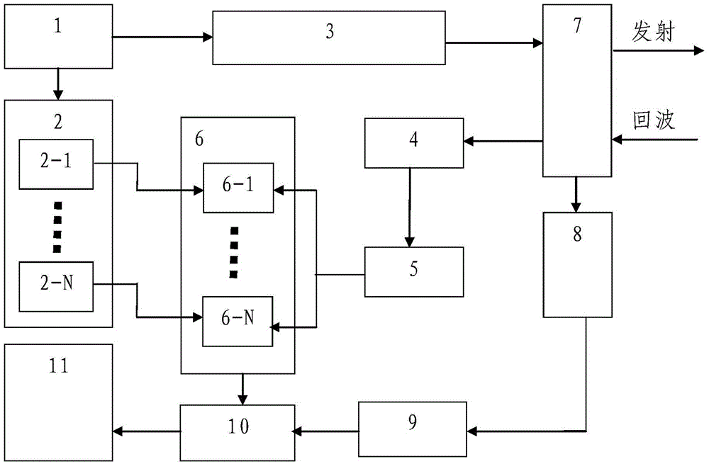
[0030] see first figure 1 , figure 1 It is a structural schematic diagram of the airborne frequency-division laser three-dimensional imaging device of the present invention. Taking two-frequency division as an example, it can be seen from the figure that the airborne frequency-division laser three-dimensional imaging device of the present invention includes a signal generator 1, a signal frequency divider 2, a laser 3. Echo detector 4, shaper 5, multi-channel time measurement circuit 6, scanning mirror 7, angle encoder 8, code counting circuit 9, data synchronous collector 10 and data processing module 11, the connection relationship of the above components as follows:

[0031] The periodic square wave generated by the signal generator 1 is input to the signal frequency divider 2 and t...


PUM


Abstract

The invention relates to an airborne frequency-division laser three-dimensional imaging apparatus. The fundamental principle is characterized in that an FPGA circuit arranged inside the apparatus carries out frequency division on a laser measurement frequency, wherein a phase difference between frequency-division signals is 2 pi/frequency division number; with a multi-channel time measurement technology, range finding is carried out on each laser measurement frequency separately; and an angle of a scanning motor is collected synchronously and synthesis of three-dimensional surface data of a measured surface is carried out. And on the basis of curvature determination of surface measurement profile data, actual three-dimensional surface data are extracted. According to the invention, one laser source and one detector are employed and the number of transmitting and receiving units does not increase. A problem of range ambiguity in airborne high-repetition-frequency laser three-dimensional imaging can be solved only by using the circuit frequency-division method; and long-distance high-repetition-frequency ambiguity-free airborne laser three-dimensional imaging is realized.

Description

technical field [0001] The invention relates to a laser radar and a laser three-dimensional scanner, in particular to an airborne frequency-division laser three-dimensional imaging device and an imaging method thereof. The device can realize airborne laser three-dimensional imaging with high repetition frequency, long distance and no distance blur. Background technique [0002] In the field of laser radar and laser 3D scanner, the commonly used laser ranging methods mainly include time-of-flight pulse direct ranging method and phase measurement method. Phase measurement is often used for short-distance measurement because the emitted laser power is low, and it is not suitable for airborne platforms. For airborne platforms with a flight altitude of more than 300 meters, laser radar or laser three-dimensional scanners are used to map the ground terrain, and pulse time-of-flight ranging methods are usually used. The distance ambiguity problem exists in the pulse time-of-flight...

Claims


Application Information

Patent Timeline
Patent Type & Authority Applications(China)
IPC IPC(8): G01S17/89
CPCG01S17/89
Inventor 贺岩胡善江臧华国陈卫标
Owner SHANGHAI INST OF OPTICS & FINE MECHANICS CHINESE ACAD OF SCI
Why Eureka
Try Eureka