Architecture for signal distribution in wireless data network

Inactive Publication Date: 2005-01-27
COMMSCOPE TECH LLC
View PDF98 Cites 33 Cited by
  • Summary
  • Abstract
  • Description
  • Claims
  • Application Information

AI Technical Summary

Benefits of technology

[0009] The present invention provides a simple and low cost architecture for coupling wireless local area network (“wireless LAN”) signals between geographically distributed access points and centrally located internetworking devices. The invention eliminates c

Problems solved by technology

This limited use has no doubt been the result of the added cost of the required wireless network adapters.
The range of a wireless LA

Method used


Image

  • Architecture for signal distribution in wireless data network
  • Architecture for signal distribution in wireless data network
  • Architecture for signal distribution in wireless data network

Examples


Example

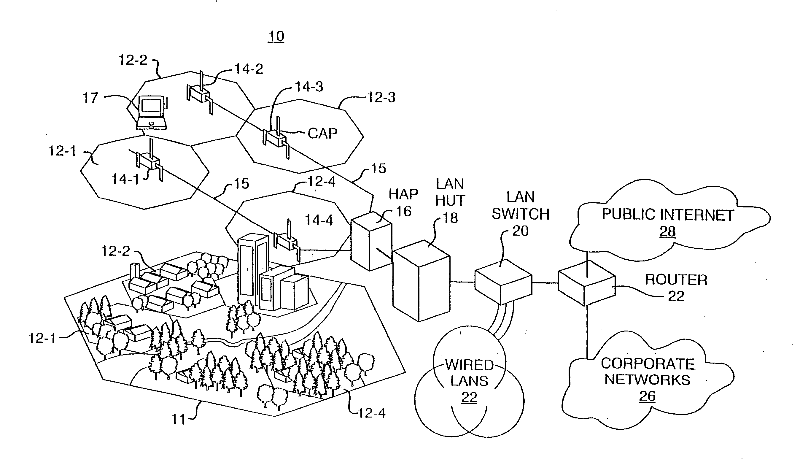
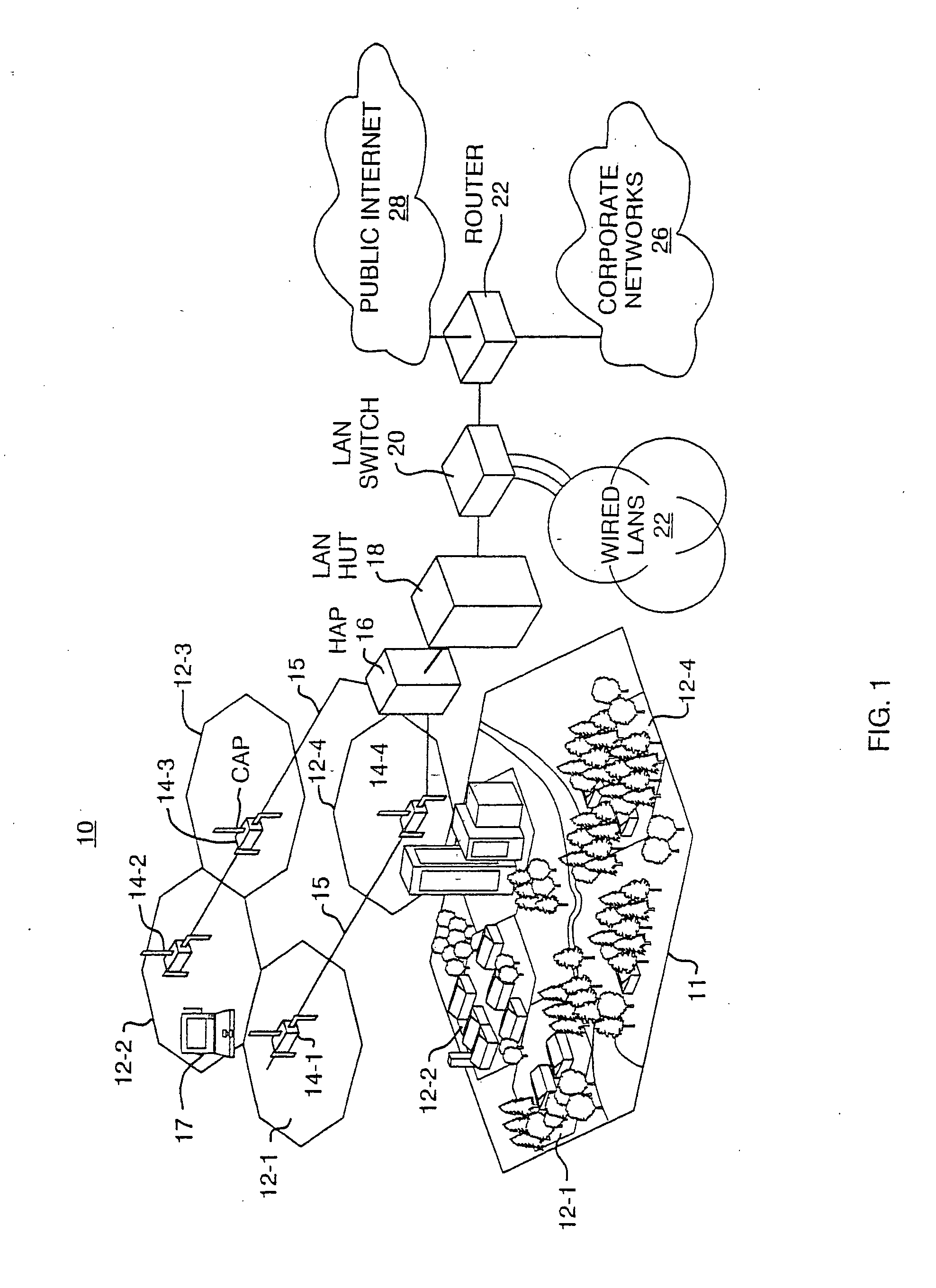
[0026] Turning attention now to the drawings, FIG. 1 is a generalized diagram of a wireless data network 10 configured according to the invention. The wireless data network 10 makes use of multiple remotely located wireless local area network (LAN) access point locations to provide wireless LAN interconnectivity over a broad coverage area. The wireless data network 10 uses widely available, already installed cabling such as a coaxial cable, optical fiber, or twisted pair as a transport medium. This architecture provides an inexpensive way to deploy wireless LAN coverage from a centralized internetworking device without the need to distribute LAN compatible cabling to each access point location in a geographic region 11.

[0027] More specifically, the wireless data network 10 consists of a number of microcells 12-1, 12-2, . . . , 12-4 distributed throughout a geographic region. Some of the microcells 12 may be located adjacent to other microcells and located in areas of particularly h...


PUM


Abstract

A simple and low cost architecture for a distribution network is provided for coupling wireless local area network (“wireless LAN”) signals between geographically distributed access points and centrally located internetworking devices. The distribution network eliminates complexities involved with the deployment of such systems in the past, which have typically required the computer network-compatible wiring to be extended to each access point directly from an internetworking device such as a repeater, bridge, router, or gateway. The distribution network makes it economically efficient to deploy wireless local area networking equipment in locations where wired network infrastructure is not readily available. In particular, any convenient existing physical wiring, such as may be provided by the existing optical transport cabling of a fiber optic network, is used as a physical layer transport medium to carry the wireless local area network signals between the access points and centrally located network hub equipment.

Description

RELATED APPLICATIONS [0001] This application is a continuation-in-part of U.S. application Ser. No. 10 / 606,655, filed Jun. 26, 2003, which is a continuation-in-part of U.S. application Ser. No. 09 / 332,518, filed Jun. 14, 1999 (now U.S. Pat. No. 6,587,479), which claims the benefit of U.S. Provisional Application No. 60 / 130,445, filed Apr. 21, 1999. The entire teachings of the above applications are incorporated herein by reference.BACKGROUND OF THE INVENTION [0002] The present invention relates generally to wireless local area network systems and more particularly to a distribution network for coupling wireless local area network signals between centrally located internetworking devices and remotely located access points. [0003] The most common user applications for personal computers now require a connection to a computer network of some type. Such applications include the viewing of e-mail, sharing of data files, and accessing the Internet and the World Wide Web. Various technique...

Claims


Application Information

Patent Timeline
IPC IPC(8): H04L12/28
CPCH04L12/2801H04W4/18H04W88/14H04W88/08H04W84/12
Inventor BIANCHI, CHARLES H.GREENWOOD, KEN C.SABAT, JOHN JR.
Owner COMMSCOPE TECH LLC
Why Eureka
Try Eureka