Offshore top site system

Active Publication Date: 2015-05-21
NAT OILWELL VARCO DENMARK
View PDF9 Cites 0 Cited by
  • Summary
  • Abstract
  • Description
  • Claims
  • Application Information

AI Technical Summary

Benefits of technology

[0015]An object of the invention is to provide an offshore top site system for deep water applications where the above described problems has been at least partly solved. It is in particular an object of the invention to provide an offshore top site system for deep water applications comprising one or more transportation lines and which is suitable for tran

Problems solved by technology

The transportation lines of such offshore top site systems are often rather heavy and provide a considerable pulling force at the point where they are connected to the floating unit.
Further, such prior art offshore system has mainly been applied on sites with only minor currents and waves and often the offshore system has been equipped with relative expensive quick-release couplings to the transportation lines, which is adapted to be released in situation of increased currents and waves.
Such turret systems are however rather expensive.
Further it has been found that such turret systems do not to a sufficient degree alleviate the movements resulting from tides and vertical movements (heave) in general.
Such a connection will inevitably be subjected to very high and often damaging stress which leads to excessive fatigue and results in the need of replacement of expensive transportation lines.
This system is however only suitable at very shallow water since the control of the SCR is very limited and the risk collision with the vessel increases with the depth of the wa

Method used


Image

  • Offshore top site system
  • Offshore top site system
  • Offshore top site system

Examples


Example

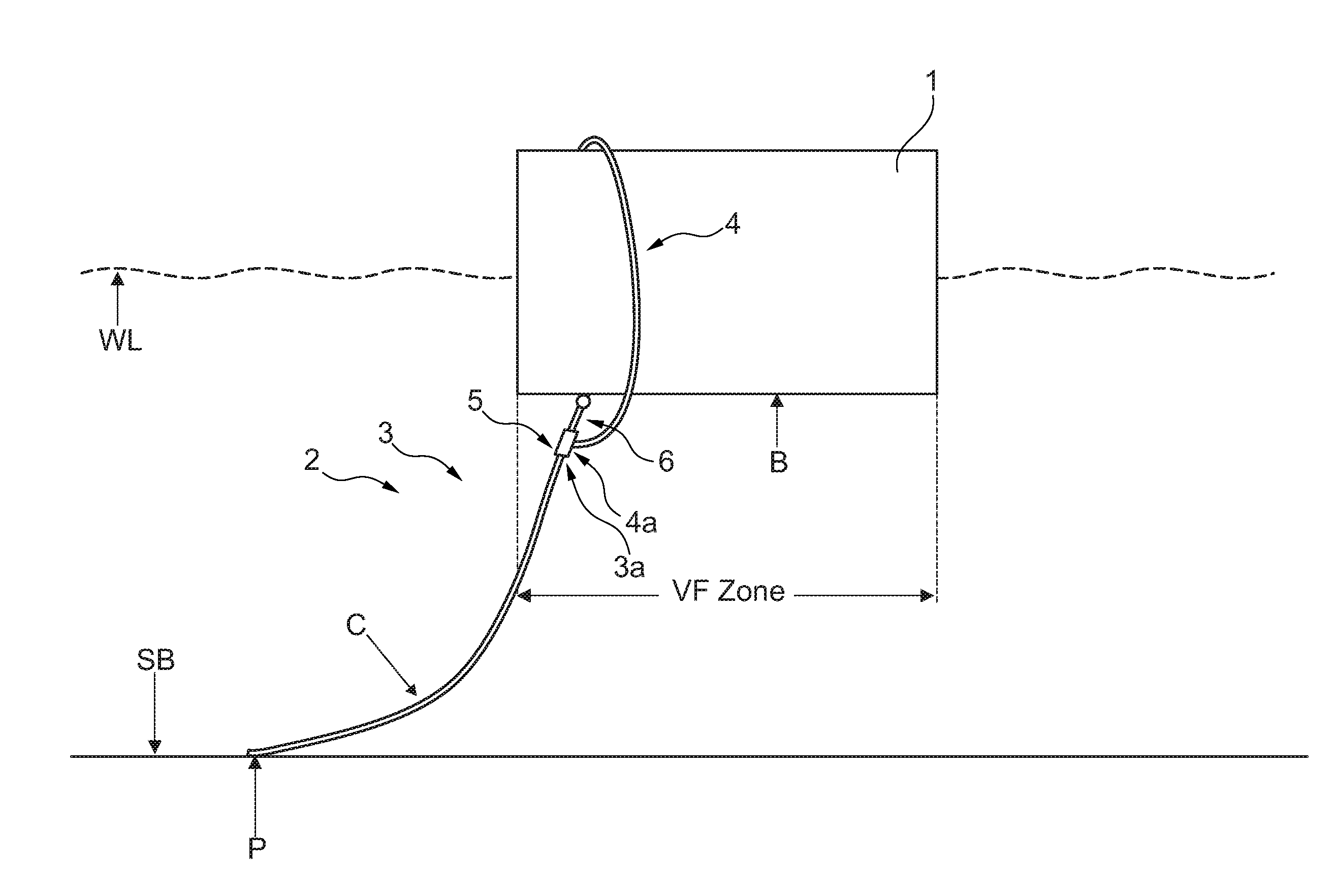
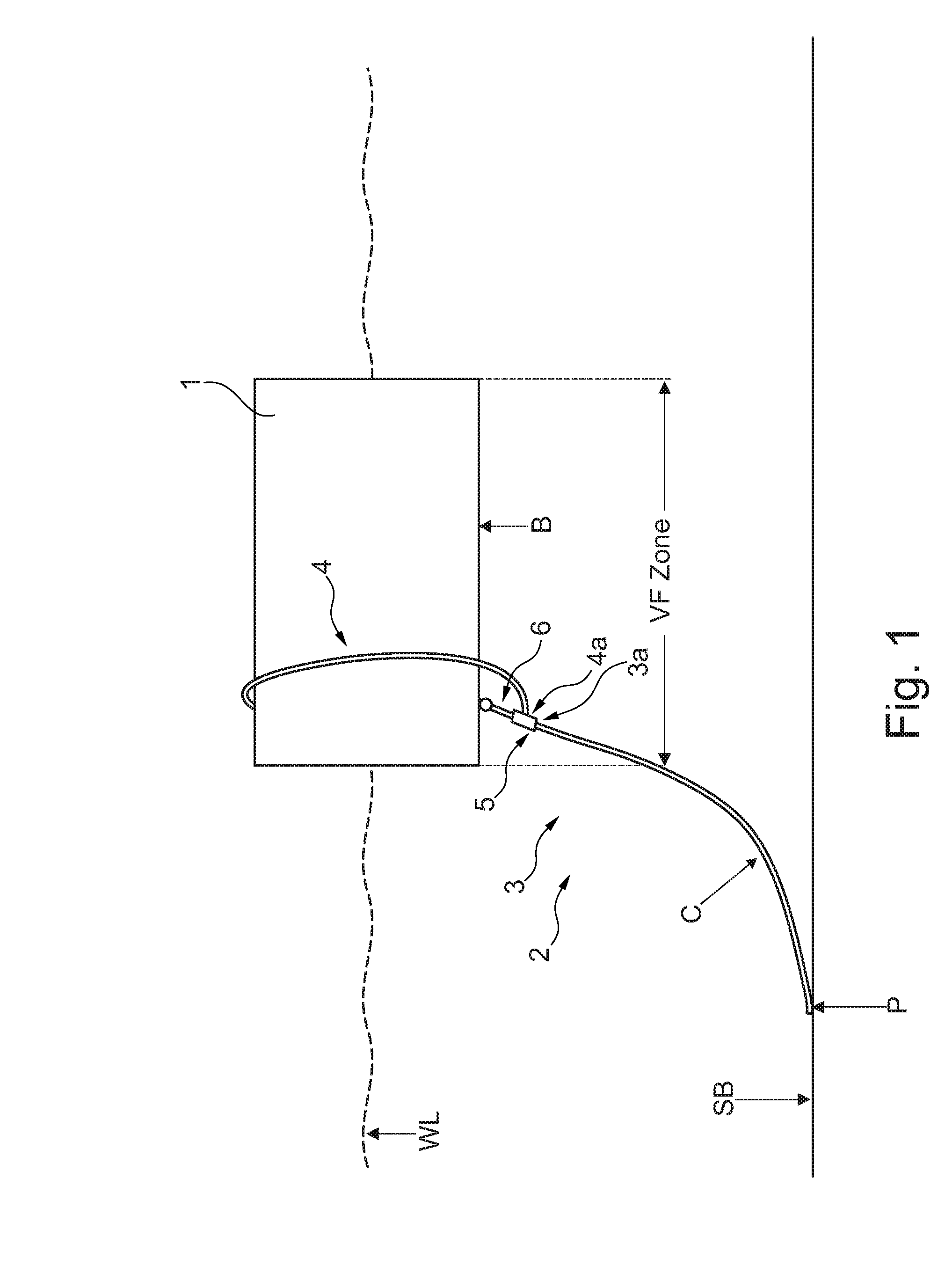
[0146]The offshore top site system shown in FIG. 1 comprises a not shown subsea facility, a floating unit 1 arranged above the subsea facility and at least one transportation line 2 extending between the not shown subsea facility and the floating unit 1.

[0147]The transportation line 2 comprises a catenary riser section 3 with an uppermost end 3a and a top site section 4 with a lowermost end 4a and the catenary riser section 3 and the top site section 4 are in flow connection with each other.

[0148]The floating unit 1 is floating at the water line WL.

[0149]As it can be seen the catenary riser section 3 extends downwards towards the seabed SB with a catenary curve C and touches the seabed SB in a touch down point P. The catenary riser section 3 leads to the not shown subsea facility which as mentioned above can be e.g. a well or a connection to another pipeline.

[0150]The top site section 4 extends upwards e.g. towards a not shown tank or similar onboard the floating unit.

[0151]The tran...


PUM


Abstract

The invention relates to an offshore top site system comprising a subsea facility, a floating unit arranged above the subsea facility and at least one transportation line extending between the subsea facility and the floating unit. The floating unit has a bottom facing downwards and an outer periphery of the bottom defining a horizontal periphery of a vertical floating unit zone VF. The transportation line comprises a catenary riser section has a length of at least about 1500 m and comprises an uppermost end and a top site section with a lowermost end. The catenary riser section and the top site section are in flow connection with each other. The transportation line further comprises a connecting portion preferably arranged within the vertical floating unit zone VF and between the top site section and the uppermost end of the riser section. The connection portion is pivotally connected to the floating unit. The connection portion is preferably pivotally connected to the floating unit such that at least a major part of pulling force from the riser section is alleviated by the connection to the floating unit.

Description

TECHNICAL FIELD[0001]The invention relates to an offshore top site system for deep water application comprising transporting flowing media such as fluids, electricity and electromagnetic signals which are transferred to or from a floating subsea facility and a floating unit floating in a position above the subsea facility, e.g. on a sea surface.BACKGROUND ART[0002]Offshore top site systems of this technical field are well known in the art. The floating unit is often a production platform or a vessel. Such floating units of offshore site systems are often referred to as FPSO units (floating production, storage and offloading units) or FSO units (floating storage and offloading units) depending on if the respective floating unit is adapted for processing hydrocarbons or not.[0003]Such offshore top site systems often comprise a plurality of transportation lines extending between the floating unit and a subsea facility such as a well, a production equipment, a mid-water arch or a simila...

Claims


Application Information

Patent Timeline
IPC IPC(8): B63B35/44B63B9/06
CPCB63B9/065B63B35/4413E21B17/015E21B19/004E21B43/0107
Inventor NIELSEN, MARTEN STORGAARD
Owner NAT OILWELL VARCO DENMARK
Why Eureka
Try Eureka