Polishing device

Active Publication Date: 2005-09-13
FLITZ INT
View PDF18 Cites 2 Cited by
  • Summary
  • Abstract
  • Description
  • Claims
  • Application Information

AI Technical Summary

Benefits of technology

[0007]The object of the present invention is to improve the above-mentioned polishing devices and to prevent any damage or scratching of the surface to be polished, in a simple and cost effective manner.

Problems solved by technology

The drawback, however, is the risk that the surfaces to be polished are scratched or damaged by the ends of the mounting arbors, screw arbors or rotating shanks, especially in the event something “slips”.

Method used


Image

  • Polishing device
  • Polishing device
  • Polishing device

Examples


Embodiment Construction

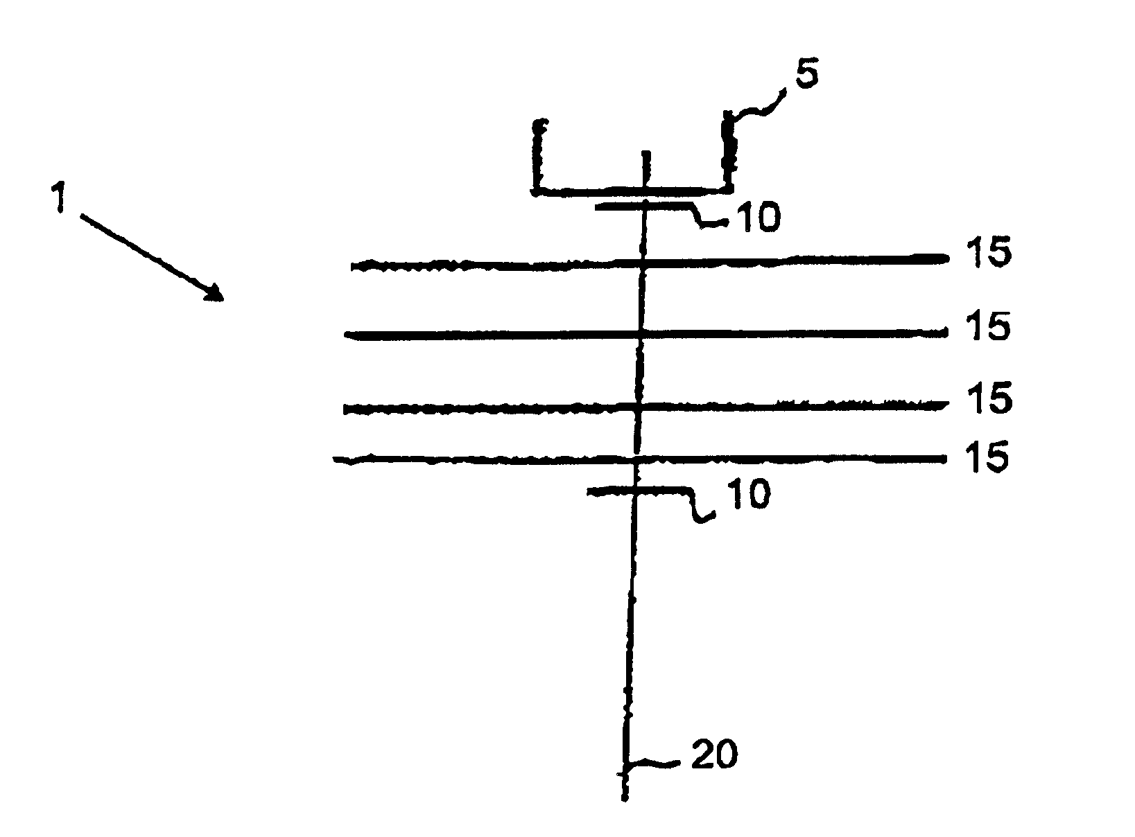
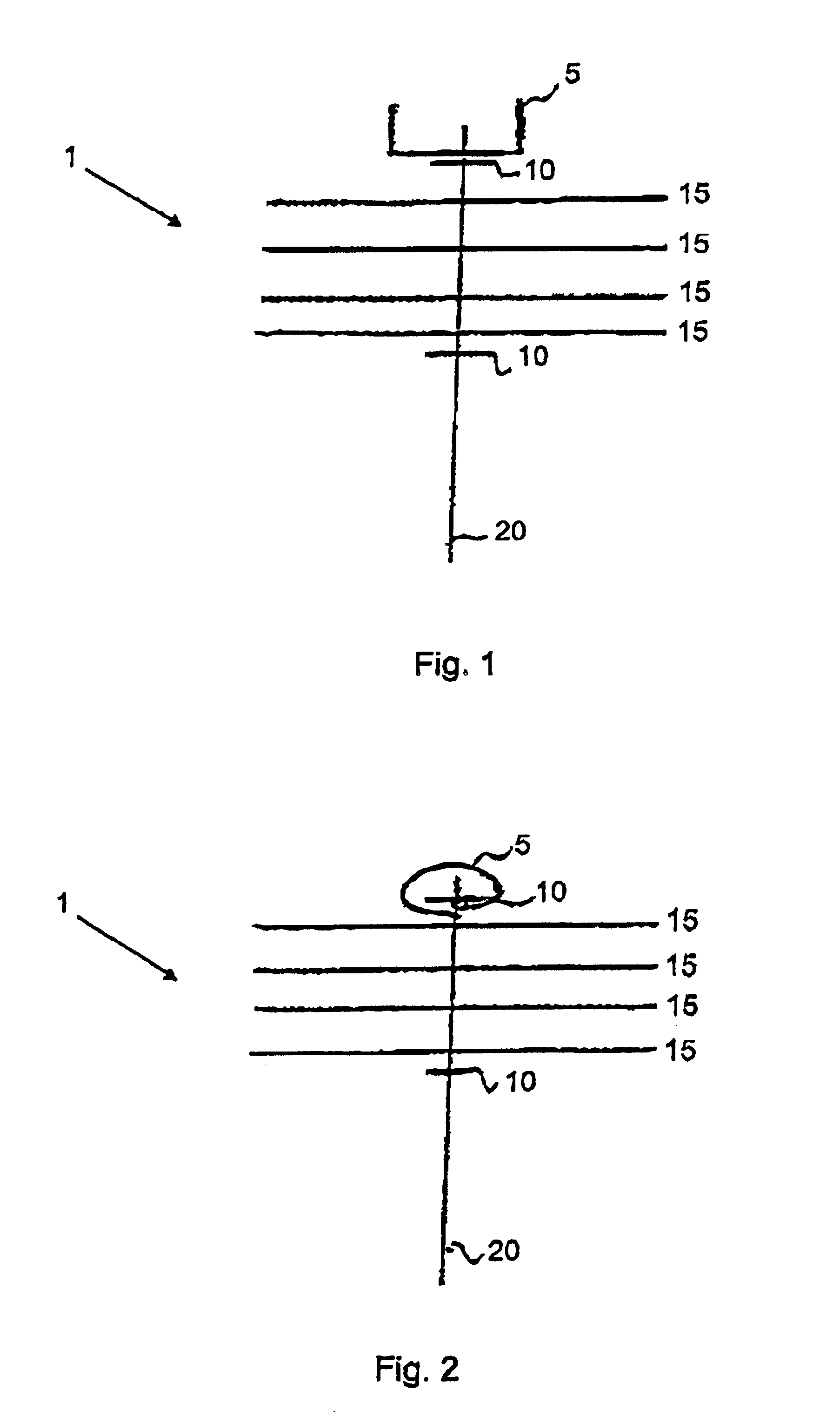
[0028]FIG. 1 shows a preferred embodiment of the polishing device 1 according to the invention. The polishing device 1 shown here consists of a shank 20, for example in the shape of a screw, polishing disks 15, two stops 10, and a protective element 5. The shank 20 is a shaft, in particular a threaded screw. The stop 10 is in the shape of a nut (with a washer, if applicable). However, it could also be a head of a screw bolt. The polishing disks 15 can be slipped through openings onto the screw 20 and fixed by means of the stop 10 which, in the present case, is a nut. The protective element 5 extends beyond the shank 20 and the stop, thus preventing direct contact with the surface to be polished. The stop at the distal end of the shaft 20 can also be in the shape of a cantilever.

[0029]FIG. 2 shows another preferred embodiment of the polishing device 1 according to the invention. The protective element 5 in this embodiment is a material sheeting made, in the present case, of the same ...


PUM

PropertyMeasurementUnit
Shapeaaaaaaaaaa
Elasticityaaaaaaaaaa
Frictionaaaaaaaaaa

Abstract

The polishing device has a shank and at least one polishing disk arranged on one end of the shank, that can be friction-fixed by two stops one opposite another. The polishing device has a protective element preventing contact between the surface to be polished and the shank end or stop.

Description

DESCRIPTION[0001]The present invention concerns a polishing device having a shank and at least one polishing disk that is arranged on one end of the shank and can be friction-fixed by two stops / bosses opposite one another.[0002]There is already a great variety of polishing devices for surface treatment. For example, felt disks, buffing disks or polishing disks are used for polishing a great variety of surfaces. Polishing disks are usually made of several layers of cloth, flat or bodied up, superimposed or stitched, to achieve surface lustre through rubbing caused by rotating polishing disks.[0003]Known are, for example, polishing devices in which the polishing body is composed of a number of superimposed and stitched cotton cloths that are arranged radially from a drill hole of a mounting arbor or screw arbor or other. In another embodiment, the polishing elements are glued to the surface surrounding a core or to a disk of a rotating work head.[0004]Such polishing devices have the a...

Claims


Application Information

Patent Timeline
IPC IPC(8): B24B55/00B24B55/04B24D13/00
CPCB24B55/04B24D13/00
Inventor KLOTZ, PETER
Owner FLITZ INT
Why Eureka
Try Eureka