
Battery Pack with Integrated Thermal Management

Pending Publication Date: 2022-03-03
L7 DRIVE OY
View PDF0 Cites 0 Cited by
  • Summary
  • Abstract
  • Description
  • Claims
  • Application Information

AI Technical Summary

Benefits of technology

The present invention provides a way to manage the temperature of a battery pack using a cheap and easy-to-install system. This is done by adding a special layer to the battery pack that has a special material that helps to keep the battery cool or hot, depending on its needs. This technology is straightforward and can improve the performance and lifespan of battery packs used in various applications.

Problems solved by technology

Swappable battery systems which provide for cost effective battery solutions have also complicated thermal management.

Method used


Image

  • Battery Pack with Integrated Thermal Management
  • Battery Pack with Integrated Thermal Management
  • Battery Pack with Integrated Thermal Management

Examples


Embodiment Construction

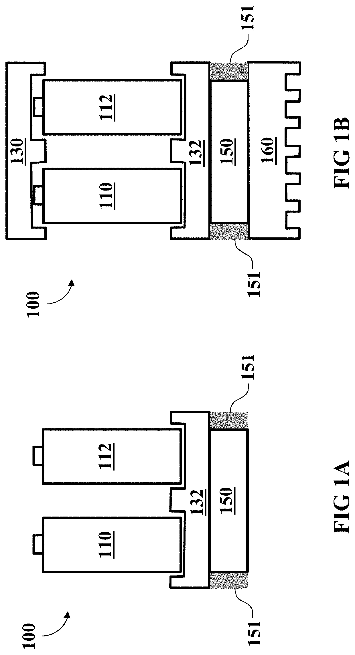
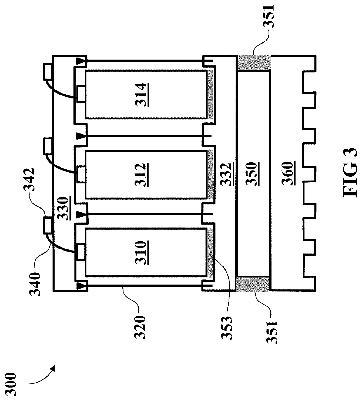
[0011]Embodiments of the present invention provide for an integrated thermoelectric element to heat and cool a battery pack. Such an integrated thermal management solution proves especially beneficial as many embodiments avoid the use of convective heating or cooling and thus allow for use in a wider range of ambient conditions. For example, a battery pack according to at least some embodiments of the present invention could maintain optimal thermal conditions for the batteries even when ambient conditions range from −40° C. to +60° C.

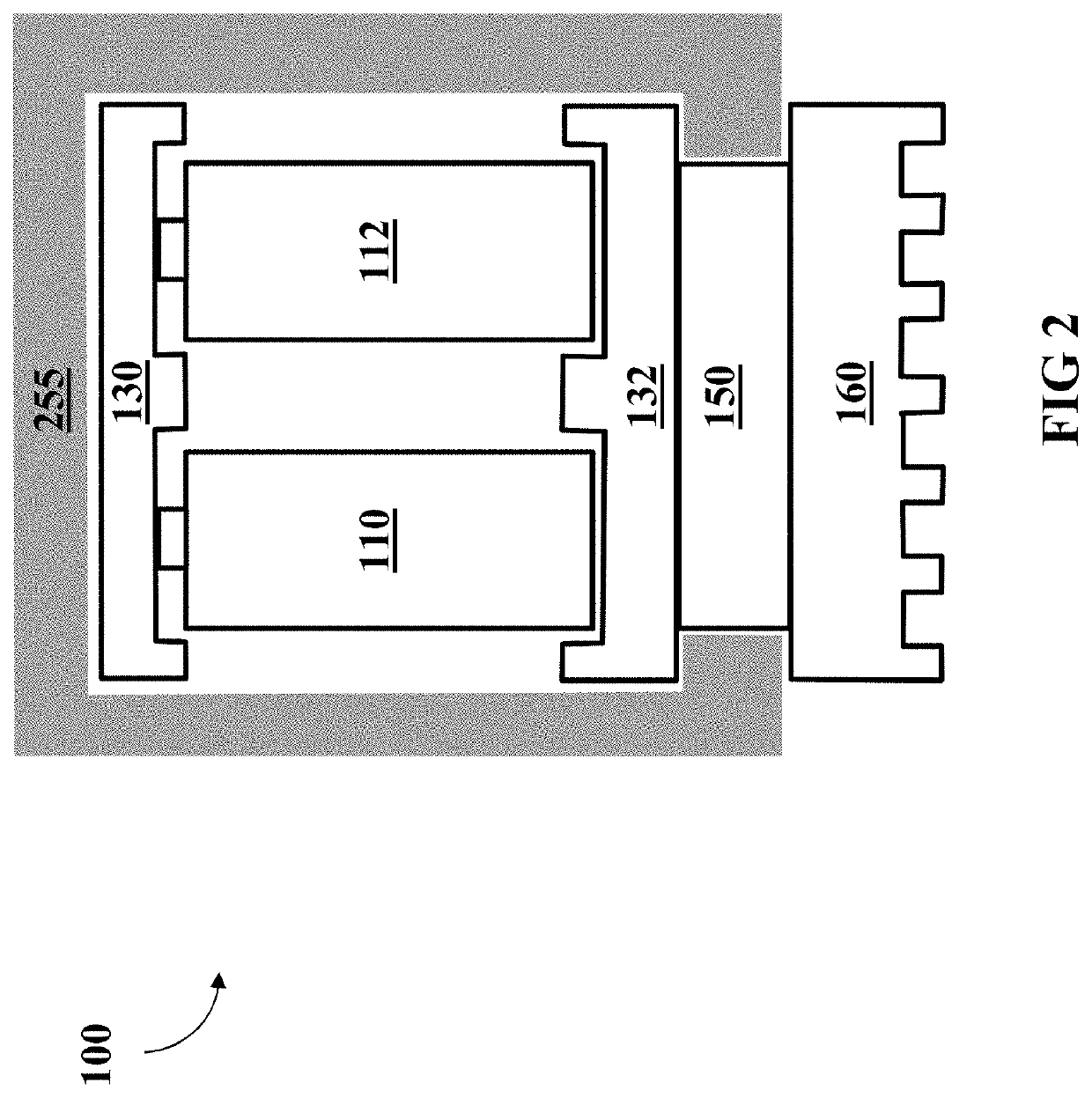
[0012]By insulating the thermoelectric element on at least two sides, battery packs having integrated thermal management according to embodiments of the present invention prevent unwanted heat transfer and allow for efficient use of a thermoelectric element.

[0013]Furthermore, embodiments of the present invention allow for thermal insulation of the majority of the battery pack such that only the heat, created by charging or discharging the battery, need...


PUM


Abstract

According to an example aspect of the present invention, there is provided a battery pack 100 having integrated thermal management. The battery pack contains a plurality of batteries 110, 112; a base plate 132 affixed to at least one terminal of each battery; a thermoelectric element 150 affixed to the base plate, and thermal insulation 151 on at least two sides of the thermoelectric element 150 adjacent the base plate 132.

Description

BACKGROUND[0001]Previously thermal management of battery packs has been provided by bulky and often unreliable systems which rely on forced air or complicated liquid cooling systems to remove heat from a battery pack under load or warm a battery pack in cold ambient conditions. Such thermal management solutions were difficult to integrate with battery packs and often were a completely separate system.[0002]Battery packs employed within light electric vehicles, especially those designed for swapping in and out of such vehicles, have provided unique problems with thermal management. The packs are often charged outside of the vehicles and as such both the battery chargers and vehicles themselves required thermal management systems. Further, battery packs designed to be easily swapped between devices often have a rather high rated current and thus produce more heat during charging and use. Despite this increased demand for thermal management, it is difficult, if not impossible to employ...

Claims


Application Information

Patent Timeline
IPC IPC(8): H01M10/6572H01M10/658H01M10/653H01M10/625H01M10/6553H01M10/643H01M10/6554H01M50/213
CPCH01M10/6572H01M10/658H01M10/653H01M50/213H01M10/6553H01M10/643H01M10/6554H01M10/625H01M10/425H01M10/486H01M10/60Y02E60/10
Inventor SALONEN, DANIEL
Owner L7 DRIVE OY
Learn More