Device and method for controlling resonant bridge power converter

A technology of power converter and control device, which is applied in the direction of output power conversion device, DC power input conversion to DC power output, control/regulation system, etc. It can solve the problem of circuit stop oscillation, fixed value, and no self-adaptation of resonant circuit components Capability and other issues, to achieve the effect of continuous operation and reliability, avoiding repeated resets

Inactive Publication Date: 2010-06-02
刘彦君
View PDF0 Cites 1 Cited by
  • Summary
  • Abstract
  • Description
  • Claims
  • Application Information

AI Technical Summary

Problems solved by technology

Most of the control devices of resonant bridge power converters on the market are voltage-controlled oscillators. The principle is as follows: the feedback voltage output from the optocoupler is connected to the RC oscillator of the controller, so that the oscillation frequency changes with the feedback voltage The upper and lower limits of frequency are set by resistors and capacitors. The disadvantage of this control method is that the values ​​of resistors and capacitors are fixed, and the output frequency range cannot adapt to the error of the frequency characteristics of the resonant tank.
In addition, the self-sustaining oscillation controller (SSOC) also does not have the ability to adapt to changes in the parameters of the resonant tank components. If the component error causes the resonant tank oscillation cycle to be too short, the variable delay module in the controller will be reset repeatedly before the delay is over. , repeated resets will cause the delay to never end, eventually causing the circuit to stop oscillating

Method used


Image

  • Device and method for controlling resonant bridge power converter
  • Device and method for controlling resonant bridge power converter
  • Device and method for controlling resonant bridge power converter

Examples


Embodiment Construction

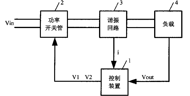
[0016] A control device for a resonant bridge power converter, such as figure 1 As shown, the signal input terminal of the control device 1 is respectively connected to the signal output terminal of the resonant circuit 3 and the load 4, the signal output terminal of the control device 1 outputs the control signal to the power switch tube 2, and the input terminal of the power switch tube 2 is connected to the DC voltage source , the power switch tube 2 for converting DC voltage into high-frequency square wave voltage, the resonant circuit 3 for transmitting high-frequency voltage and generating close to sine wave current, and the power switch tube 3 for converting high-frequency voltage into DC voltage or other forms of energy The load 4 is connected in series, and the control device 1 for detecting voltage and current waveforms is provided with a period measurement module 8 and a time-limiting module 9 inside.

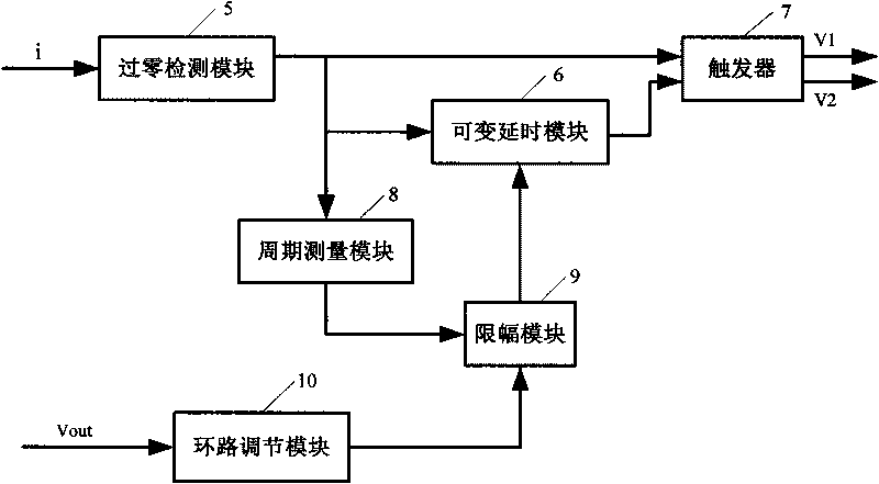
[0017] Such as figure 2 As shown, the control device 1 also i...


PUM


Abstract

The invention relates to a device for controlling a resonant bridge power converter. The signal input terminal of the device is connected with the signal output terminals of a resonance circuit and a load respectively, and the signal output terminal of the device outputs a control signal to a power switching tube; the input terminal of the power switching tube is connected with a DC (direct current) voltage source; the power switching tube, the resonance circuit and the load are connected in series; and a cycle measurement module and a timing module are arranged inside the device used for detecting the voltage and current waveform. The invention further discloses a method for controlling a resonant bridge power converter. By adding the cycle measurement module used for measuring the cycle of the change in the direction signal of the resonant current outputted by the resonance circuit and the timing module used for limiting the delay time, the invention can ensure that the limited delay time is smaller than half the oscillation period of the resonance circuit and the variable delay always ends before the direction of the resonant current is changed, thus preventing the variable delay module from repeatedly resetting.

Description

technical field [0001] The invention relates to a resonant bridge power converter, in particular to a control device and a control method for the resonant bridge power converter. technical background [0002] At present, there are many kinds of control devices for resonant bridge power converters, among which voltage-controlled oscillators and self-sustaining oscillator controllers (SSOC) are the most common. Most of the control devices of resonant bridge power converters on the market are voltage-controlled oscillators. The principle is as follows: the feedback voltage output from the optocoupler is connected to the RC oscillator of the controller, so that the oscillation frequency changes with the feedback voltage However, the upper and lower limits of frequency are set by resistors and capacitors. The disadvantage of this control method is that the values ​​of resistors and capacitors are fixed, and the output frequency range cannot adapt to the error of the frequency cha...

Claims


Application Information

Patent Timeline
IPC IPC(8): H02M3/24
Inventor 刘彦君
Owner 刘彦君
Why Eureka
Try Eureka