Valves

A valve hole and valve seat technology, applied in the direction of control valves, valve devices, functional valve types, etc., can solve problems such as mechanism failure

Inactive Publication Date: 2010-06-02
ANSON LTD
View PDF0 Cites 10 Cited by
  • Summary
  • Abstract
  • Description
  • Claims
  • Application Information

AI Technical Summary

Problems solved by technology

However, such a simple mechanism is prone to failure when the internal vessel pressure is high

Method used


Image

  • Valves
  • Valves
  • Valves

Examples


Embodiment Construction

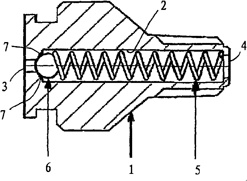
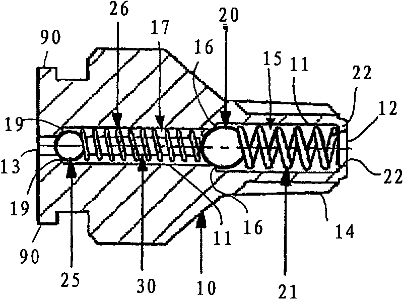
[0044] figure 2 A cross-sectional view of a valve according to one embodiment of the invention is shown. The valve comprises a valve body 10 through which a valve bore 11 passes from a first valve opening 12 to a second valve opening 13 .

[0045] The outer surface of the valve body adjacent to and surrounding the first valve opening defines a nozzle 14 extending in a direction parallel to the axis of the valve bore. The outer surface of the nozzle is threaded to enable the nozzle to be coupled into a correspondingly threaded aperture in a container or cavity wall to couple and form a sealing fit with the valve body to the container or cavity. The end surface of the nozzle is shaped to define a first valve opening which, in use, is used to allow a substance (eg, a pressurized fluid) to enter the valve from a container or cavity to which the valve is coupled. In the hole, and let the substance (for example, lubricant) to be injected into the container or cavity through the v...


PUM


Abstract

A double check valve (10) with two separate elements (20, 25) individually movable to close the valve and collectively movable to open the valve. The separate elements are independently closing the valve, and collectively controllable to open the valve, to allow pressure release or to allow injection of fluid (e.g. lubricant). In an example, the double check valve includes two separate check valves with a stinger element (30) between them which is operable to internally sting the one check valve when (e.g. by action of) the other check valve is stung by a user (e.g. using a stinger means) thereby to open both check valves individually and the double check valve as a whole.

Description

technical field [0001] The present invention relates to valves, such as check valves, and particularly, but not exclusively, to lubricating accessories for lubricating pressurized containers or cavities. Background technique [0002] There are currently many different types of lubricating accessories that provide a means of injecting lubricant into a pressurized container while also providing a means of retaining the lubricant within the container involved. For example, a lubricating accessory that fits onto a container to be lubricated inside can act as a simple check valve that allows lubricant to flow from a valve opening on the outside of the container to a valve opening on the inside of the container, thereby forcing the lubricating The lubricant is passed from the outer opening to the inner opening and thereafter into the container itself, allowing the lubricant to be injected into the container. Many such valves include a simple one-way check valve mechanism that all...

Claims


Application Information

Patent Timeline
Patent Type & Authority Applications(China)
IPC IPC(8): F16K15/04
CPCF16K15/042Y10T137/0318Y10T137/7837Y10T137/7846Y10T137/87917Y10T137/88038Y10T137/88046F16K15/066
Inventor R·W·安德森N·C·肯尼迪
Owner ANSON LTD
Why Eureka
Try Eureka