Method for sampling secondary loop in power system with optimized measurement accuracy

A secondary circuit and power system technology, applied in the direction of measurement using digital measurement technology, can solve the problems of measuring small current errors, parameter measurement system parameter calculation distortion, and narrow current output range, so as to eliminate interference and improve measurement accuracy Effect

Active Publication Date: 2011-10-19
SHENZHEN SHUANGHE ELECTRIC CO LTD
View PDF3 Cites 0 Cited by
  • Summary
  • Abstract
  • Description
  • Claims
  • Application Information

AI Technical Summary

Problems solved by technology

[0002] The secondary output signal of the current transformer on the primary side of the substation is divided into two types: the protection signal and the measurement signal, each of which uses its own transformer. The two have completely different output working ranges and precisions. The protection signal is characterized by relatively Wide current output range, within the output range, it can measure large currents with high accuracy, while small currents have low accuracy; the characteristic of the measurement signal is that the current output range is narrow, and within the output range, it can measure small currents with high accuracy, while large currents have low accuracy
[0003] Secondary monitoring devices in the power system, such as line wave recording, main transformer wave recording, unit wave recording, PMU, power quality monitoring and transmission line parameter synchronization measurement, etc., are connected to the protection circuit of the power system. The measurement accuracy is high, and the accuracy of small current signals is low. The error of measuring small currents may easily cause problems such as inaccurate ranging and positioning of the wave recorder, insufficient accuracy of the PMU phase angle, and distortion of the parameter calculation of the parameter measurement system.

Method used


Image

  • Method for sampling secondary loop in power system with optimized measurement accuracy
  • Method for sampling secondary loop in power system with optimized measurement accuracy
  • Method for sampling secondary loop in power system with optimized measurement accuracy

Examples


Embodiment Construction

[0021] The present invention will be further described below in combination with specific embodiments and with reference to the accompanying drawings.

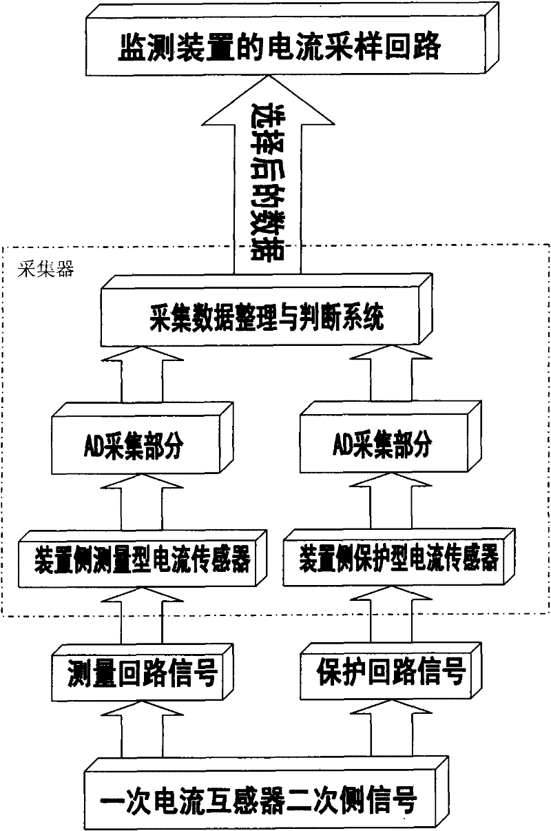
[0022] The implementation of the present invention in the traditional substation is as follows: figure 1 shown. Connect the current signal of the protection circuit and the measurement circuit to the measuring current transformer on the device side and the protection current transformer on the device side at the same time, use two AD acquisitions to collect the output of the two transformers, and then collect the results by The collected data sorting and judging system judges and selects, and obtains the final collection result for the current sampling loop of the monitoring device.

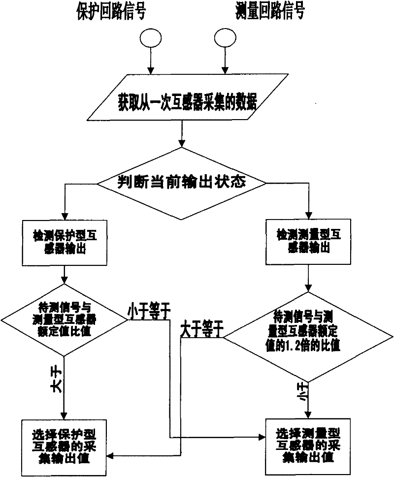
[0023] The working logic of its data collection and judgment system is as follows: figure 2 shown. The collection data collection and judgment system of the collector judges and selects the collection results of the two channels. The collecto...


PUM


Abstract

The invention discloses an optimized sampling method for an acquisition device of a secondary loop of a power system. A current signal of a measuring loop and a current signal of a protecting loop are synchronously introduced through a data acquisition unit; an acquired data reduction and judgment system in the acquisition unit performs analysis and selection so as to select corresponding sampling loop signals as input data of a monitoring device. The method, as a measuring plan with low cost and high precision, is capable of completely combining output results of two mutual inductors in a mode of software switching, which eliminates interferences brought by traditional hardware circuit switching, makes up for precision shortages when existing acquisition devices sample low magnitude of current, and effectively improves the measuring precision within a full range. Furthermore, the method can be widely applicable to various devices such as a line oscillograph, a main variation oscillograph, a set oscillograph, a PMU, a power quality and transmission line parameter synchronously measuring device, and to analog quantity sampling when the two or more device functions synchronously exist in a device with multiple functions.

Description

technical field [0001] The invention relates to monitoring and recording, in particular to a sampling method for optimizing the measurement accuracy of a secondary circuit of a power system. Background technique [0002] The secondary output signal of the current transformer on the primary side of the substation is divided into two types: the protection signal and the measurement signal, each of which uses its own transformer. The two have completely different output working ranges and precisions. The protection signal is characterized by relatively Wide current output range, within the output range, it can measure large currents with high accuracy, while small currents have low accuracy; the characteristic of the measurement signal is that the current output range is narrow, and within the output range, it can measure small currents with high accuracy, while large currents have low accuracy . [0003] Secondary monitoring devices in the power system, such as line wave reco...

Claims


Application Information

Patent Timeline
Patent Type & Authority Patents(China)
IPC IPC(8): G01R19/25
Inventor 熊敏俊赵忠
Owner SHENZHEN SHUANGHE ELECTRIC CO LTD
Why Eureka
Try Eureka