
Blind source separation method based on mixed signal local peak value variance detection

A local peak, mixed signal technology, applied in speech analysis, instruments, etc., can solve the problems of inability to effectively detect local peaks of signal attenuation, inaccurate estimation of mixing matrix parameters, and low estimation accuracy of source signals.

Inactive Publication Date: 2012-01-18
HARBIN INST OF TECH
View PDF0 Cites 0 Cited by
  • Summary
  • Abstract
  • Description
  • Claims
  • Application Information

AI Technical Summary

Problems solved by technology

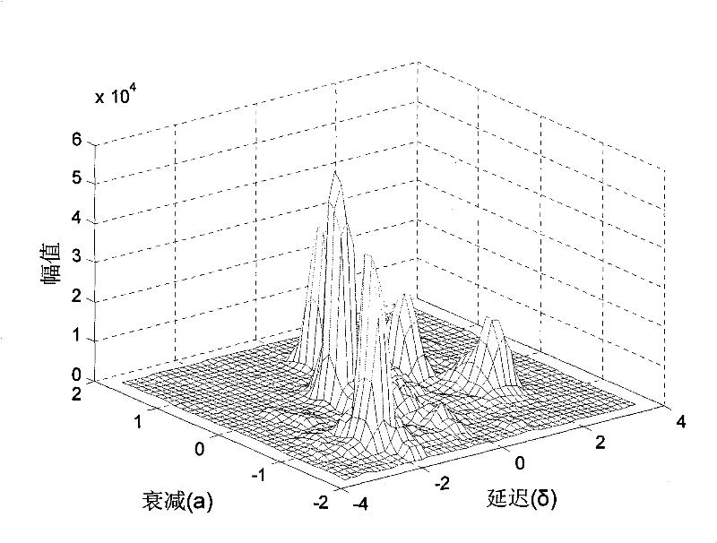
[0028] In order to solve the problem that the current DUET blind source separation method cannot effectively detect local peaks in the signal attenuation-delay histogram and estimate the parameters of the mixing matrix inaccurately, resulting in low accuracy of source signal estimation, a method based on local peak variance of mixed signals is proposed Blind source separation method for detection (Sub-area variance peak detection, SV-peakdet)

Method used


Image

  • Blind source separation method based on mixed signal local peak value variance detection
  • Blind source separation method based on mixed signal local peak value variance detection
  • Blind source separation method based on mixed signal local peak value variance detection

Examples


specific Embodiment approach 1

[0047] Specific implementation mode one: combine figure 1 In this embodiment, the blind source separation method based on the local peak variance detection of the mixed signal is realized based on the following system: the blind source separation system is composed of a mixing system and an unmixing system, and the source signal s f (t) and the noise signal v e (t) mixed in the hybrid system, the observed signal through the hybrid system is x e (t), observed signal x e (t) The estimated signal of the source signal separated by the unmixing system is Among them, the observed signal x e (t) and the noise signal v e (t) represents the observation signal and noise signal of the eth sensor, and the source signal s f (t) represents the fth source signal, the estimated signal Represents the estimated signal of the fth source signal, and 1≤f≤P, where P represents the number of source signals.

[0048] The specific steps of the blind source separation method based on local pea...

specific Embodiment approach 2

[0067] Specific embodiment 2: This embodiment further defines step C in specific embodiment 1. In step C, a threshold value threshold δ is set, and the peak sub-region Further screening, select the value a of the center point (i,j) Peak sub-regions greater than the threshold threshold δ Participate in subsequent calculations, that is, satisfy a (i,j) ≥δ peak subregion Participate in subsequent calculations.

[0068] In this embodiment, the threshold δ of the maximum value is manually adjusted and set by technicians according to the actual demand of the signal. Generally, the threshold δ is proportional to the maximum amplitude M in the signal attenuation-delay histogram. For example, the threshold δ of the maximum value in this embodiment can be selected

[0069] In this embodiment, according to the set threshold threshold δ, the peak sub-region After further screening, only the value a of the center point (i,j) It is the maximum value in this sub-region and the su...

specific Embodiment approach 3

[0070] Specific implementation mode three: this implementation mode is a further limitation of step E in specific implementation mode one, in step E, all peak sub-regions The variance of VAR k The method of sorting adopts the "bubble method".


PUM


Abstract

The invention discloses a blind source separation method based on mixed signal local peak value variance detection, relating to the improvement on a DUET method and solving the problem that the peak value can not be effectively detected in the prior DUET blind source separation method, in particularly comprising the following steps: finding out all N*N grid subregions on a signal source attenuation-delay column diagram; selecting out the subregion of which the value of the central point is maximum in all subregions as the peak value subregion; respectively calculating the average value of thethree-dimensional coordinates of all data points in the selected peak value subregion, sequentially solving the distances from each data point to the average value point and calculating variances; sequencing all variances, and extracting the first P larger variances; and transferring the horizontal coordinates and vertical coordinates corresponding to the P peak values to an attenuation-delay array, extracting the peak value by binary time-frequency masks, separating signal sources on the time-frequency domain, and transforming to time domain to obtain the final separation source signals. Themethod is applicable to general peak value detection, in particular applicable to the peak value detection of the DUET blind source separation method.

Description

technical field [0001] The invention relates to the technical field of blind source separation, in particular to the improvement of the local signal peak detection method of the DUET blind source separation method in time-frequency component analysis. Background technique [0002] Blind Source Separation (BSS) refers to recovering or separating out only the aliasing signal observed by the sensor according to the statistical characteristics of the input source signal without knowing the prior information of the source signal and the transmission channel. process of the source signal. Due to its special properties, it has broad practical application prospects in many fields such as wireless communication, array signal processing, biomedical signal processing, voice signal processing and image signal processing. [0003] At present, the independent component analysis (Independent Component Analysis, ICA) method is applied to most blind source separation problems, but this meth...

Claims


Application Information

Patent Timeline
Patent Type & Authority Patents(China)
IPC IPC(8): G10L21/02G10L21/0272
Inventor 付宁乔立岩彭喜元曹离然
Owner HARBIN INST OF TECH
Learn More