Camera pose determination method, device, electronic device, and computer-readable medium
A camera and pose technology, applied in the computer field, can solve the problem of poor camera pose estimation effectiveness, and achieve the effect of alleviating the poor estimation effectiveness.
- Summary
- Abstract
- Description
- Claims
- Application Information
AI Technical Summary
Problems solved by technology
Method used
Image
Examples
Embodiment 1
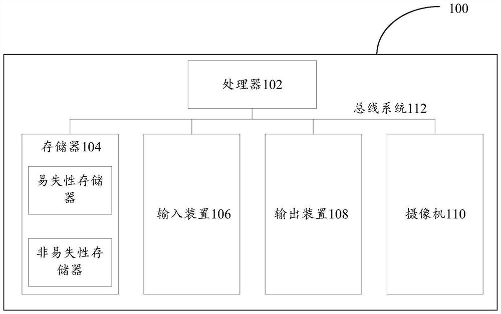
[0027] First, refer to figure 1 The electronic device 100 for implementing the embodiment of the present invention can be used to operate the camera position determination of the embodiments of the present invention.
[0028] like figure 1 As shown, the electronic device 100 includes one or more processor 102, one or more memory 104, input device 106, output device 108, and camera 110, which are connected by bus systems 112 and / or other forms of connection mechanisms (not shown) Interconnection. It should be noted that figure 1 The components and structures of the electronic device 100 shown are merely exemplary, not limiting, and the electronic devices may also have other components and structures.
[0029] The processor 102 can be implemented using at least one of the digital signal processor (DSP), field programmable gate array (FPGA), programmable logic array (PLA), and ASIC (Application Specific Integrated Circuit). The processor 102 may be a central processing unit (CPU) o...
Embodiment 2
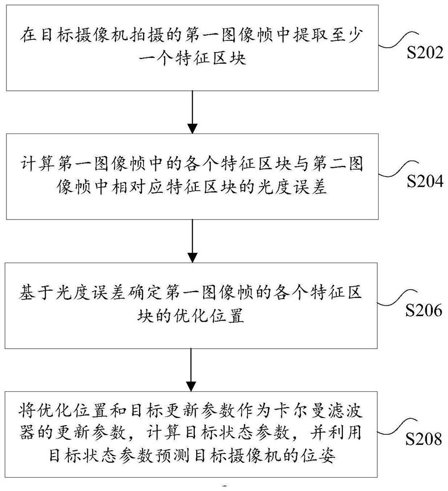
[0036] According to an embodiment of the present invention, an embodiment of a camera position determining method is provided, and it is to be explained that the steps shown in the drawings can be performed in a computer system such as a set of computer executable instructions. Although the logical order is shown in the flowchart, in some cases, the steps shown or described may be performed in the order herein.
[0037] figure 2 It is a flow diagram of a method for determining a method according to an embodiment of the present invention, such as figure 2 As shown, the method includes the following steps:
[0038] Step S202, extract at least one feature block in the first image frame captured by the target camera;
[0039] In the present embodiment, the first image frame is an image frame to be processed at the current time, and the second image frame is a first image frame of the first image frame.
[0040] The feature block in the first image frame and the feature in the second ...
Embodiment 3
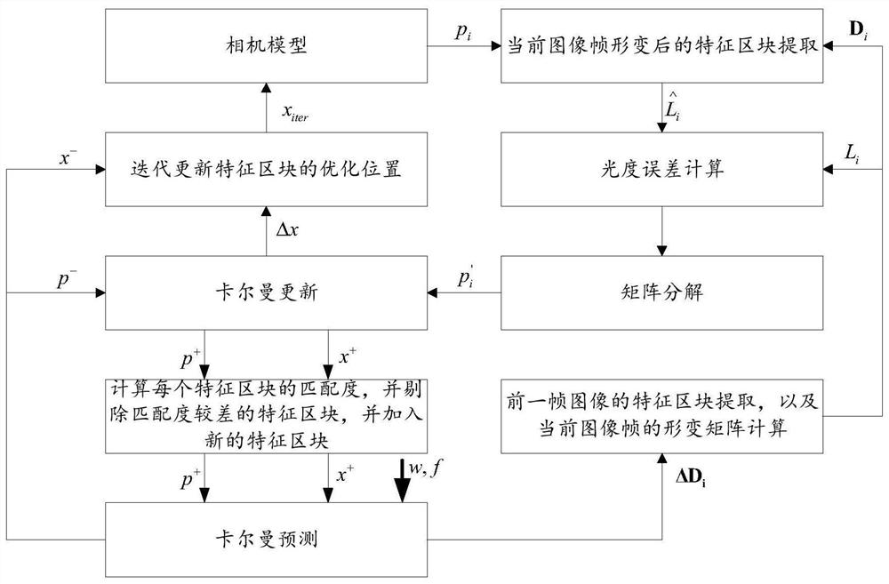
[0088] image 3 It is a flow chart of another camera position determination method according to an embodiment of the present invention, such as image 3 As shown, the process of this method is as follows:
[0089] (1) System initialization. Get initialization of the Calman filter by obtaining the acceleration W of the camera to obtain the angle speed f of the camera by the inertial measuring unit of the camera to obtain the second parameter P + , X + Where the second parameter P + , X + For the previous frame image, the covariance and the system status amount after Karman update;
[0090] (2) Calman predicts. By initializing the second parameter, the acceleration W input after initialization, the corner speed F is predicted on the status of the current camera, resulting in P - X - The specific calculation process is described below:
[0091] The formula of the current camera acceleration and angular velocity is: in, Measure the angular velocity, The true value of angular velocit...
PUM
 Abstract
Description
Claims
Application Information
 - R&D
- Intellectual Property
- Life Sciences
- Materials
- Tech Scout
- Unparalleled Data Quality
- Higher Quality Content
- 60% Fewer Hallucinations
Browse by: Latest US Patents, China's latest patents, Technical Efficacy Thesaurus, Application Domain, Technology Topic, Popular Technical Reports.
© 2025 PatSnap. All rights reserved.Legal|Privacy policy|Modern Slavery Act Transparency Statement|Sitemap|About US| Contact US: help@patsnap.com


