Noise elimination brake for automatic spindle locking mechanism

A spindle and automatic technology, applied in the direction of motor tools, manufacturing tools, portable motor devices, etc., can solve the problems that cannot be incorporated into rotary power tools, etc., and achieve the effect of convenient and repeatable design

Inactive Publication Date: 2010-06-09
ROBERT BOSCH GMBH
View PDF2 Cites 4 Cited by
  • Summary
  • Abstract
  • Description
  • Claims
  • Application Information

AI Technical Summary

Problems solved by technology

[0004] A disadvantage in prior art solutions is that the structure is a complete design which cannot be easily incorporated into existing rotary power tools without extensive redesign

Method used


Image

  • Noise elimination brake for automatic spindle locking mechanism
  • Noise elimination brake for automatic spindle locking mechanism
  • Noise elimination brake for automatic spindle locking mechanism

Examples


Embodiment Construction

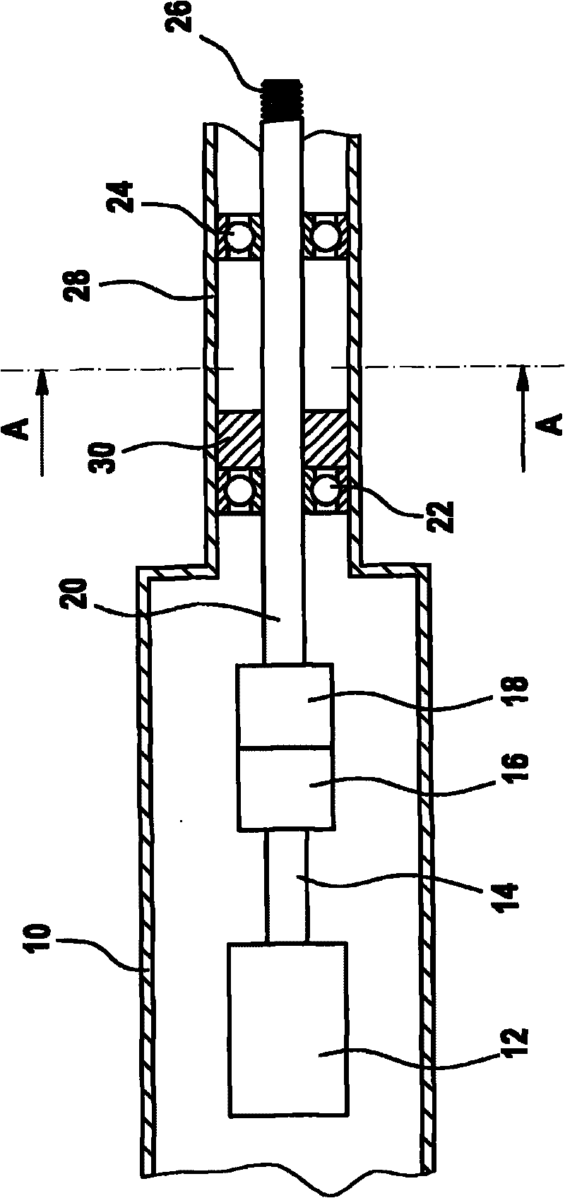
[0017] A part of a rotary power tool (in particular a drill / screwdriver) according to the invention is attached figure 1 is shown schematically. The power source for this tool is usually AC or DC batteries. Located within the rotary power tool housing 10 is a motor 12 and its associated motor shaft 14, which is driven by the power source. Generally, the transmission 16 regulates the speed and torque transmitted by the motor shaft 14 to downstream elements of the powertrain.

[0018] An automatic spindle locking mechanism (ASLM) 18 is located downstream of the transmission 16 . ASLM is well known in the art and the details of how it works will not be described in detail in the present invention. For examples of different ASLMs, the reader is referred instead to US Patent Nos. 6311787 and 2006 / 0131043A1, which are hereby incorporated by reference. As is often the case in the prior art, the transmission 16 is not necessarily separate from the ASLM 18 . That is, it is possibl...


PUM


Abstract

A rotary power tool comprising a motor (12), a motor shaft (14) driven by the motor, an output shaft coupled to the motor shaft via an automatic spindle locking mechanism (18), a housing portion surrounding the output shaft, and a braking member that is non-rotatable relative to the housing portion, wherein the braking member exercises a braking torque on the output shaft (20) whenever it rotates.

Description

technical field [0001] This invention relates to rotary power tools and in particular to those power tools equipped with automatic spindle locking mechanisms (ASLM). When the motor is at rest, the ASLM resists rotation of the output shaft of the rotary tool in response to an externally applied torque, such as from rotation of a tool chuck coupled to the output shaft. In recent years, a number of different couplings have been used, but generally the configuration is such that rotation of the motor shaft drives the output shaft, while rotation of the output shaft does not drive the motor shaft, instead causing engagement of the ASLM. Background technique [0002] The motor shaft and output shaft of the power tool with ASLM are generally coupled together but with some rotational play remaining between the coupling parts. The undesirable consequences of this ASLM configuration arise when the motor shaft slows down after the motor is turned off. Because of the inertia of the ou...

Claims


Application Information

Patent Timeline
Patent Type & Authority Applications(China)
IPC IPC(8): B25B21/00B25F5/00
CPCB25F5/001
Inventor C·H·梁J·姚E·H·陈T·马蒂斯O·泽特D·布罗格利A·施韦杰
Owner ROBERT BOSCH GMBH
Why Eureka
Try Eureka