Novel bearing removal method

A bearing disassembly device and bearing technology, applied in the fields of connection, disassembly or clamping, and fastening, to achieve the effects of improving operating efficiency, reducing preparation requirements, and reducing difficulty

Active Publication Date: 2012-10-10
BAOSHAN IRON & STEEL CO LTD
View PDF5 Cites 0 Cited by
  • Summary
  • Abstract
  • Description
  • Claims
  • Application Information

AI Technical Summary

Problems solved by technology

This kind of operation obviously has its disadvantages: firstly, it is not safe, and secondly, it is easy to bring shaft damage and slag into the equipment, and it is quite time-consuming and laborious
[0011] To sum up, the above-mentioned conventional devices have the following problems when used for bearing dismounting: either a larger working space is required, or additional assistance such as a claw mechanism is required Mechanism, it is difficult to apply to the situation where the space around the bearing is extremely small, and the angular contact ball bearings installed in pairs back to back are disassembled
Therefore, it is urgent to design a new type of bearing removal device, which can solve the problem of bearing removal when the axial and radial space positions of the inner bearing of the shaft end are very small, and can solve the paired angular contact of the back-to-back installation form. Disassembly of ball bearings

Method used


Image

  • Novel bearing removal method
  • Novel bearing removal method
  • Novel bearing removal method

Examples


Embodiment 1

[0048] Embodiment 1: New bearing removal device (when using a jack):

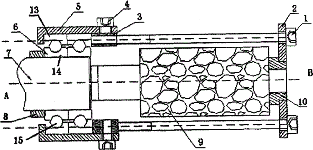
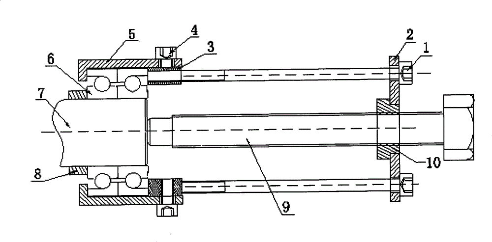
[0049] The novel (multifunctional) bearing removal device of the present invention comprises: 1—M12*160 inner hexagonal bolt; 2—top plate; 3—drawing claw fixing ring; 4—M12*25 inner hexagonal bolt; 5—arc-shaped pulling claw; 10 -Nut ring.

[0050] Three hexagon socket bolts 1 pass through the top plate 2 and arrange three through holes at 120°. The threads of the head of the hexagon socket bolt 1 are screwed into the claw fixing ring 3 and three M12 threaded through holes are arranged at 120° in the axial direction. In this way, the most stable and reliable mechanical mechanism is formed structurally.

[0051] step 1:

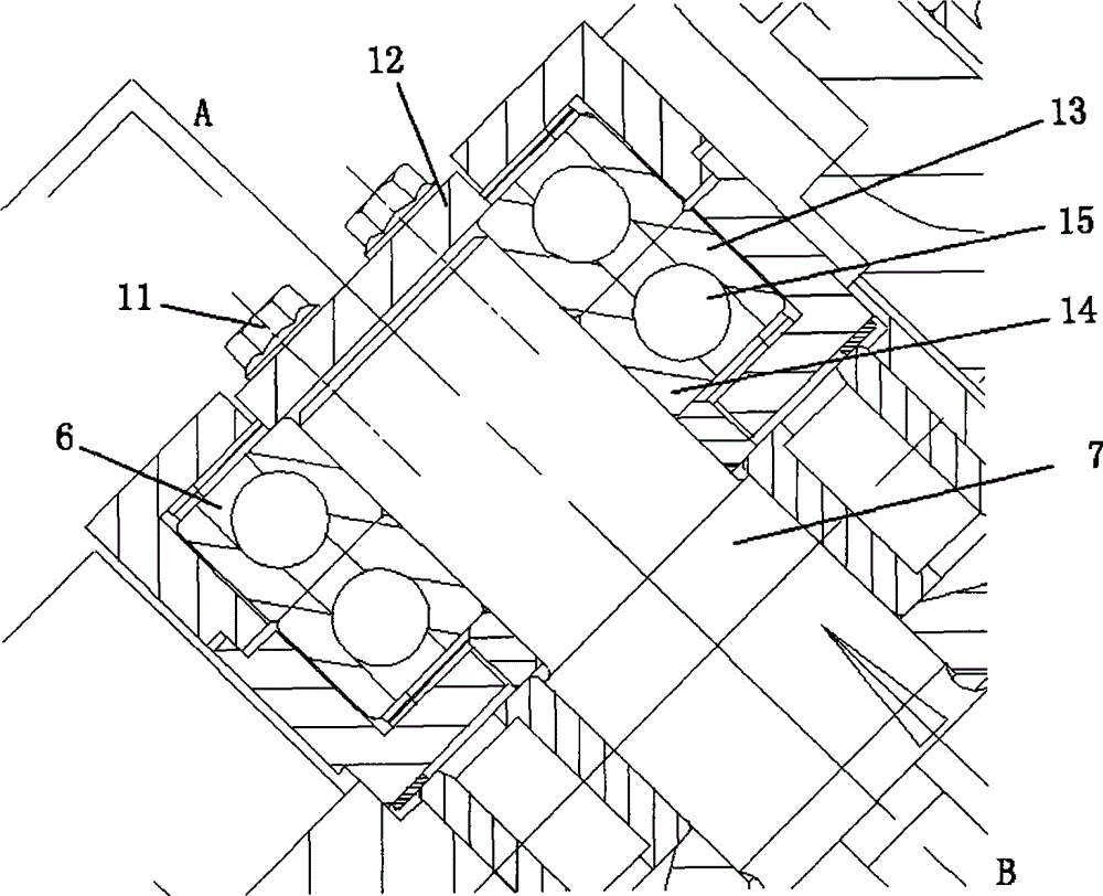
[0052] Disassemble the shaft end pressure plate bolt 11 and the shaft end pressure plate 12, pull out the upper bearing seat and the lower bearing seat, and now only a pair of bearings are left at the shaft end, and then the bearing can be disassembled with the bearing dismounting device ...

Embodiment 2

[0063] Embodiment 2: Work when using bolts instead of hydraulic jacks:

[0064] Like embodiment 1, the difference is that the bolt 9' of M24 is used instead of the hydraulic jack to work, and its working principle is the same as above, wherein the nut ring 10 and the bolt 9' of M24 use the torque generated when the thread works to complete the disassembly work. This allows operation without hydraulic jacks, increasing its flexibility and practicality.

[0065] The structure that the nut ring 10 and the top plate 1 are designed into two bodies is to reduce the weight of the whole top plate while ensuring the bearing capacity of the thread. After many times of use, if the thread is damaged, you only need to replace the thread and ring instead of the entire top plate, which can reduce the consumption of metal raw materials and reflect the idea of ​​energy saving.

[0066] In the above embodiment, when the bearing is disassembled by the new type bearing dismounting device of the ...


PUM


Abstract

The invention relates to a novel bearing removal method and a device thereof, which is used for removal of an angular contact ball bearing which is provided with a small circumferential space and is assembled in a back-to-back way; the bearing removal device comprises a pull claw fixing ring (3), an arc-shaped pulling claw (5) which is arranged on the pull claw fixing ring and is provided wit a protruded hook part at one end for hooking a bearing outer ring (13), and a top plate (2) which is fixedly treaded with the pull claw fixing ring (3) by a bolt (1) and is arranged at the other end; a hydraulic jack (9) is arranged in the pull claw fixing ring in a run-through way, the working end of the hydraulic jack pushes against to one end of the bearing, under the action of the hydraulic jack,an outer ring (13) of another (left side or right side) bearing and one bearing (right side or left side) move to right outwards together, so as to remove a shaft system, a rolling body (15) and a retainer drop off owning to no binding of the bearing outer ring, only an inner ring (14) of the bearing is left, and then the arc-shaped pulling claw (5) is removed, an inner hexagonal tightening screwor a bolt (4) is used to push against to the bearing inner ring (14), and under the action of the hydraulic jack, so as to remove to right outwards.

Description

technical field [0001] The present invention relates to a method and its device for fastening, connecting, disassembling or clamping, in particular, the present invention relates to a method and its device specially suitable for the assembly or separation of deformed or non-deformed parts or articles , more specifically, the present invention relates to a bearing dismounting method and device thereof, which can be conveniently used for dismounting angular contact ball bearings with extremely small space around the bearing and installed in pairs back to back. Background technique [0002] The finishing mill and reducing sizing mill in the high-speed high-speed area of ​​metallurgical equipment are installed obliquely at 45°. Whenever it is necessary to repair or replace a pair of back-to-back angular contact ball bearings at the end of the output spiral bevel gear shaft, Because the axial and radial spatial positions of a bearing on the inner side of the shaft end are very s...

Claims


Application Information

Patent Timeline
Patent Type & Authority Patents(China)
IPC IPC(8): B25B27/02B25B27/06
Inventor 张建平
Owner BAOSHAN IRON & STEEL CO LTD
Why Eureka
Try Eureka