
Swivel clamp for overhead transmission line spacer

A technology of overhead transmission lines and swivel lines, applied in the direction of the device for maintaining the distance between parallel conductors, etc., can solve the problems of discontinuous and unsmooth rotation, and achieve the effect of flexible and reliable rotation and simple structure

Active Publication Date: 2011-12-28
CHINA ELECTRIC POWER RES INST +1
View PDF1 Cites 0 Cited by
  • Summary
  • Abstract
  • Description
  • Claims
  • Application Information

AI Technical Summary

Problems solved by technology

The middle swivel clamp realizes the rotation by sliding, which is prone to the problem of discontinuous and unsmooth rotation

Method used


Image

  • Swivel clamp for overhead transmission line spacer
  • Swivel clamp for overhead transmission line spacer
  • Swivel clamp for overhead transmission line spacer

Examples


Embodiment Construction

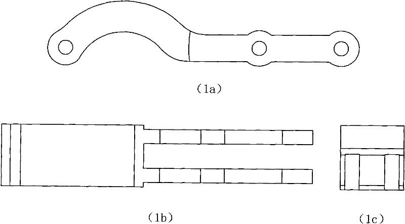
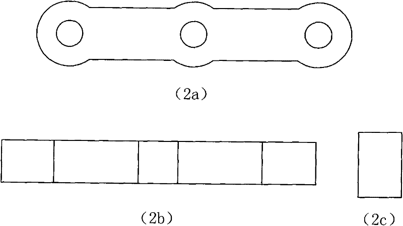
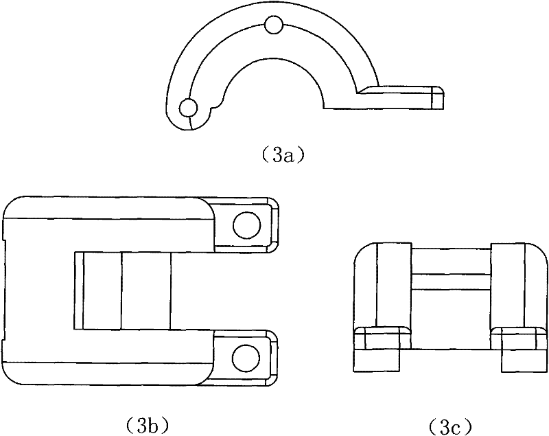
[0032] like figure 1 Shown is a three-dimensional schematic view of the rotary clamp used for overhead transmission line spacers according to the present invention. The rotary clamp body includes a semicircular arc-shaped first line clamp chuck 4 and a semicircular arc-shaped second wire clamp chuck 5 , two arc-shaped first rotary rods 6 and two linear second rotary rods 7, the first wire clamp chuck 4 is hinged with the two first rotary rods 6, and the second wire clamp chuck 5 is hinged with two second rotary rods 7, the two first rotary rods 6 are hinged with two second rotary rods 7, and the two second rotary rods 7 are hinged with the clamp support body 3; the first The two rotary rods 7 rotate in a circle with their own symmetrical center as the axis. The two first rotary rods 6, the two second rotary rods 7, the first wire clamp chuck 4, and the second wire clamp chuck 5 form a fixed movement. The four-bar mechanism of the track, the first wire clamp chuck 4 and the s...


PUM


Abstract

The invention provides a rotary clamp for overhead transmission line spacers, which has a clamp support body and a rotating clamp body, the clamp support body is fixedly connected to the spacer body, and the rotating clamp body includes a semicircular The first wire clamp chuck, the second semi-circular arc-shaped clamp chuck, two circular-arc-shaped first rotary rods and two linear second rotary rods; the second rotary rod is made with its own symmetrical center Circumferential rotation, through the four-bar mechanism of the fixed motion track, the wire clip chuck clamps the wire, and realizes free rotation with the center of the wire as the axis. The design of the rotary clamp abandons the previous design idea that the rotary chuck realizes the rotation by sliding, and solves the problem that the chuck rotation is easy to be discontinuous and not smooth when the sliding method makes the chuck rotate.

Description

technical field [0001] The invention relates to the field of power system devices, in particular to a rotary clamp for spacer rods of overhead power transmission lines. Background technique [0002] There are few types of swivel clamps actually used in overhead transmission lines in my country, and the structure is single. At present, the domestic construction of 1000kV UHV transmission line demonstration projects adopts the spacer bar in the form of a rotary clamp. The rotary clamp includes two clamps: the first clamp and the second clamp with slide rails. Sliding occurs between the second wire clip with the slide rail and the slide block fixedly connected to the body of the spacer bar. Achieves centerline rotation gripped with the first clamp and the second clamp with slide rail. This kind of rotary clamp is described in detail in Chinese patent: 200820108710.6. It is a rotary clamp for overhead transmission line spacers. The rotary clamp is composed of a clamp support b...

Claims


Application Information

Patent Timeline
Patent Type & Authority Patents(China)
IPC IPC(8): H02G7/12
Inventor 朱宽军牛海军刘胜春孙娜李新民
Owner CHINA ELECTRIC POWER RES INST
Learn More